Variable-diameter bearing inner ring induction replacer
A disassembler and ring induction technology, applied in metal processing equipment, metal processing, manufacturing tools, etc., can solve the problems of difficult to control heating temperature, low efficiency, shaft and bearing damage, etc., to achieve easy control of surface temperature and reduce use. Cost, the effect of quick and non-destructive disassembly
- Summary
- Abstract
- Description
- Claims
- Application Information
AI Technical Summary
Problems solved by technology
Method used
Image

Examples
Embodiment Construction
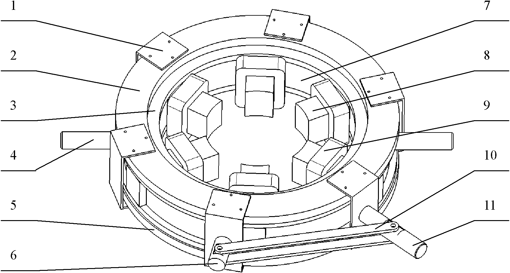
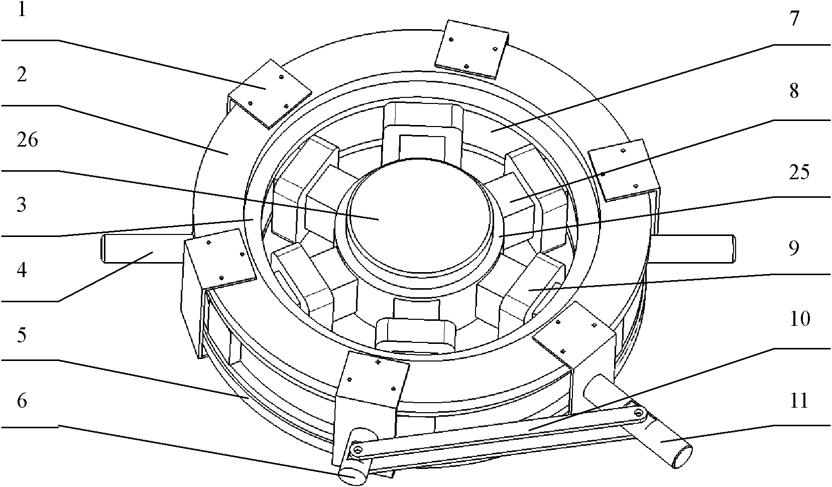
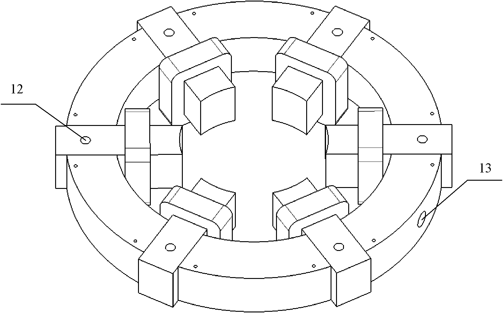
[0034] In the present invention, six radial magnetizers 8 and six circumferential magnetizers 7 are arranged at intervals in turn to form a circumferential group of magnetizers. Six coils 9 are respectively sleeved on six radial magnetizers 8, and two fixing rings 3 are respectively located on the magnetizers. The upper and lower sides of the circumference group; the front radial adjustment ring 2 and the reverse radial adjustment ring 5 are respectively located on both sides of the two fixing rings 3, and the six fixing clips 1 are connected with the front radial adjustment ring 2 and the reverse radial adjustment ring 5 fixed, and evenly distributed in the circumferential direction; the two handles 4 are screwed to the circumferential guide magnet hole 13 on the circumferential guide magnet 7, and are symmetrically distributed about the center of the circle, and the fixed rod 6 and the clamping rod 11 are fixedly connected to the fixed clamp respectively 1, the two ends of th...
PUM
 Abstract
Description
Claims
Application Information
 - Generate Ideas
- Intellectual Property
- Life Sciences
- Materials
- Tech Scout
- Unparalleled Data Quality
- Higher Quality Content
- 60% Fewer Hallucinations
Browse by: Latest US Patents, China's latest patents, Technical Efficacy Thesaurus, Application Domain, Technology Topic, Popular Technical Reports.
© 2025 PatSnap. All rights reserved.Legal|Privacy policy|Modern Slavery Act Transparency Statement|Sitemap|About US| Contact US: help@patsnap.com