Mechanical arm device of centerless grinding machine

A technology of centerless grinding machines and manipulators, applied in the direction of manipulators, program-controlled manipulators, grinding machines, etc., can solve the problems of difficult machining accuracy and low machining efficiency, and achieve the effects of ensuring product quality, reducing scrap rate, and preventing radial runout

Active Publication Date: 2011-05-25
常州市武滚轴承有限公司
View PDF8 Cites 8 Cited by
  • Summary
  • Abstract
  • Description
  • Claims
  • Application Information

AI Technical Summary

Problems solved by technology

Figure 10 What is shown is a torsion bar of an electric power steering system. The rod body is not cylindrical, but is composed of multiple concentric but unequal diameter cylinders. For this type of combination of multiple concentric but unequal diameter cylinders At present, the segmented grinding method is adopted for the slender shaft. For the combined slender shaft with high precision requirements, the traditional processing method is difficult to guarantee the required processing accuracy, and the processing efficiency is low. The profile plate is used to trim the shape of the grinding wheel and guide wheel on the grinding machine, and the above-mentioned combined slender shaft is processed by profiling one-time grinding, which needs to solve the loading and unloading problem. At present, there is no combined slender shaft loading and unloading suitable for centerless grinding machines. device

Method used


Image

  • Mechanical arm device of centerless grinding machine
  • Mechanical arm device of centerless grinding machine
  • Mechanical arm device of centerless grinding machine

Examples


Embodiment 1

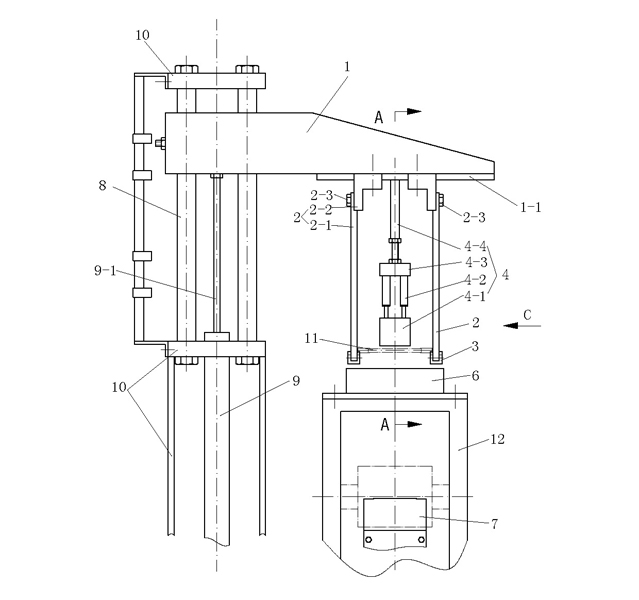
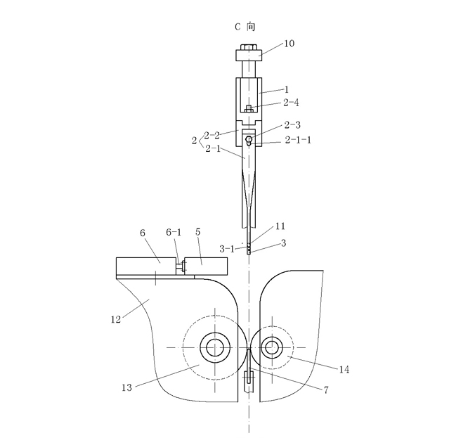
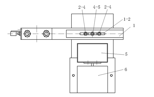
[0026] See Figure 1 to Figure 9 , this embodiment includes a pallet 7 fixed on the main machine frame and between the grinding wheel 13 and the guide wheel 14, and also includes a bracket 10 fixed on the main machine frame, a hydraulic cylinder 9 fixed on the bottom of the bracket 10, and a A pair of guide posts 8 on the top of the support 10 and a lifting seat 1 that is driven by the piston rod 9-1 of the hydraulic cylinder 9 to slide along the above-mentioned pair of guide posts 8, a pair of mechanical arms 2 are arranged on the lifting seat 1, and the two mechanical arms The thickness h of the lower part of the arm 2 is smaller than the diameter of the workpiece, and an elastic pressing plate assembly 4 is provided on the lifting base 1 and between the two mechanical arms 2 .

[0027] The casing 12 above the grinding wheel of the main machine is provided with a cylinder 6, and the piston rod of the cylinder 6 is connected to a receiving box 5. When the two mechanical arms ...


PUM


Abstract

The invention discloses a mechanical arm device of a centerless grinding machine, which comprises a supporting plate, a bracket fixed on a main machine rack, a hydraulic cylinder fixed on the lower part of the bracket, a pair of guide pillars fixed on the upper part of the bracket and a lifting seat for driving the pair of guide pillars to slide by a piston rod of the hydraulic cylinder. A pair of mechanical arms for arranging work pieces on the supporting plate is arranged on the lifting seat. The thicknesses of the lower parts of the two mechanical arms are smaller than that of the work piece. An elastic pressure plate component is arranged between the two mechanical arms on the lifting seat. The device has a simple structure; and the pair of mechanical arms supports the two ends of each work piece to realize loading and unloading, and is driven by the hydraulic cylinder, so that the loading and unloading are more stable and accurate and entire-shaft profiling can be realized. The device solves the problem that the conventional centerless grinding machine cannot machine a combined slender shaft consisting of a plurality of concentric cylinders with different diameters, and compared with the conventional device utilizing ordinary external grinding, improves the machining accuracy and reduces the rejection rate.

Description

technical field [0001] The invention relates to a centerless grinder, in particular to a centerless grinder manipulator. Background technique [0002] The centerless grinding machine adopts centerless clamping, and the workpiece is placed between the grinding wheel and the guide wheel, and is supported by the supporting plate and the guide wheel. At present, for the grinding of short cylindrical rotary workpieces such as bearing rollers, automatic loading and unloading can be realized by loading and unloading devices. The Chinese Patent No. 200820233899.1 utility model patent specification discloses an automatic loading and unloading device for a centerless grinder, which has an inclined feeding chute installed above the grinding wheel, and the outlet of the feeding chute is at the outlet of the feeding chute 1. A feeding push rod driven by the feeding power device that can move up and down is installed directly above the processing station, and a horizontally moving discha...

Claims


Application Information

Patent Timeline
Patent Type & Authority Applications(China)
IPC IPC(8): B24B5/18B25J9/02B25J9/08
Inventor 周国通
Owner 常州市武滚轴承有限公司
Why Eureka
Try Eureka