
Biomass pyrolyzing furnace

A biomass pyrolysis and furnace shell technology, which is applied in the direction of biofuel, coke oven, special form of dry distillation, etc., can solve the problems of low production efficiency, low yield of biomass charcoal and wood tar, and high production cost

Active Publication Date: 2011-05-25
湖南国雄新能源科技有限公司
View PDF6 Cites 13 Cited by
  • Summary
  • Abstract
  • Description
  • Claims
  • Application Information

AI Technical Summary

Problems solved by technology

This kind of biomass fuel pyrolysis equipment has the following disadvantages: 1. It needs to be pried every few hours, which is labor-intensive and unsafe; 2. The biomass pyrolysis time is long, the production efficiency is low, and the production cost is high; 3. The output of material charcoal and wood tar is small, and a large amount of charcoal fuel is turned into wood gas and wood vinegar, which leads to a large waste of raw materials
In order to ensure the cooling effect, the recovery tower is often heightened by about 20 to 50 meters. Due to the short distance between the bottom of the tower and the ground, once the pipeline of the recovery tower is blocked by wood tar, it is not convenient to use tools to clear the pipeline.

Method used


Image

  • Biomass pyrolyzing furnace
  • Biomass pyrolyzing furnace
  • Biomass pyrolyzing furnace

Examples


Embodiment Construction

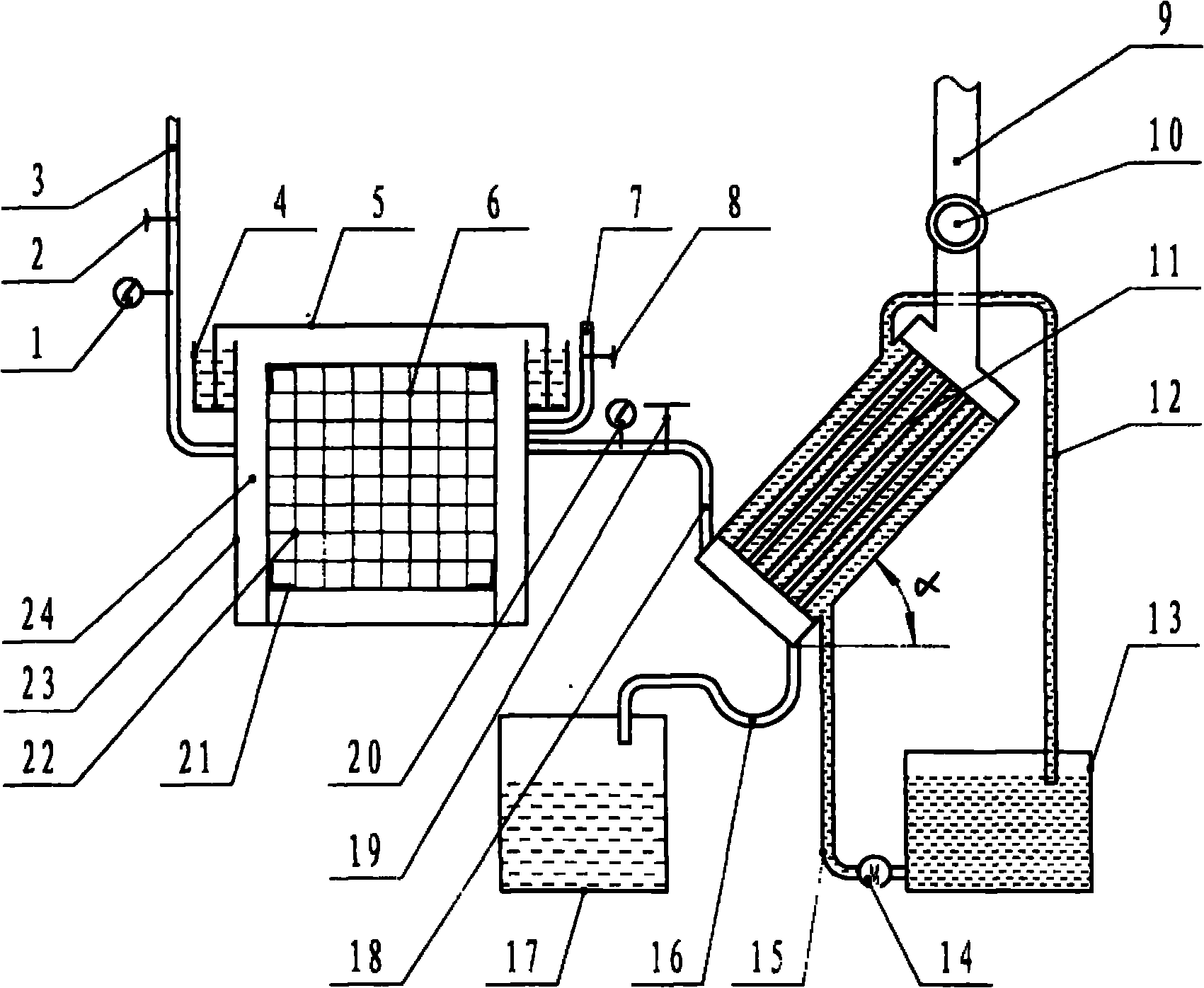
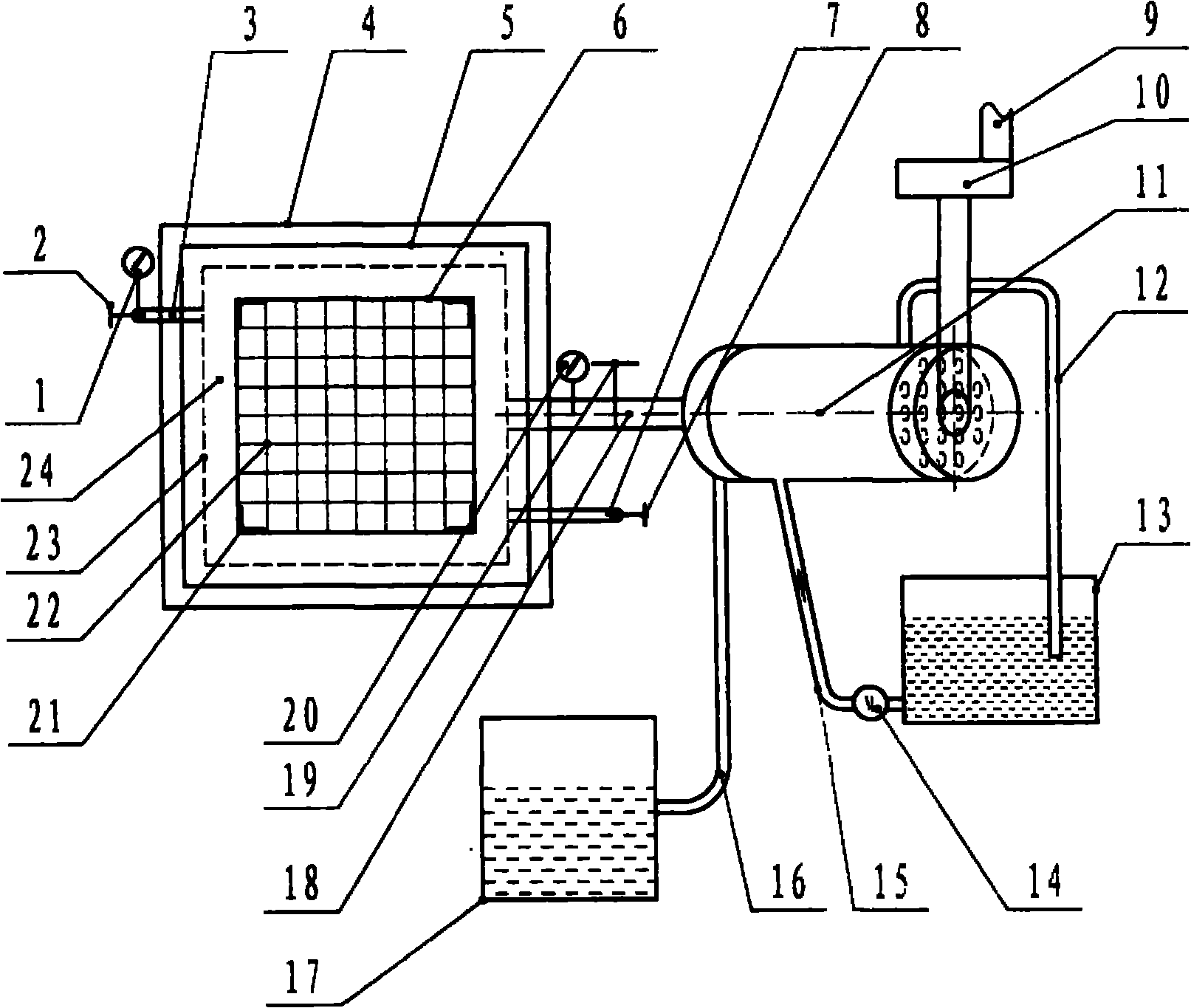
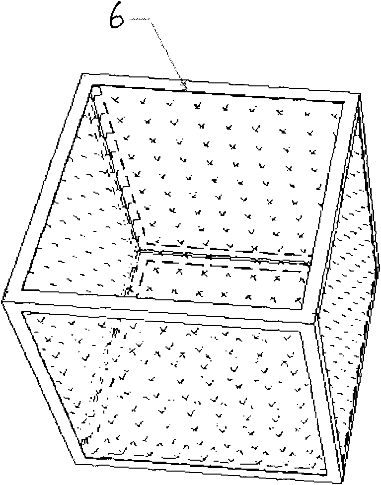
[0015] Thermometer 1, switch 2, exhaust pipe 3, U-shaped water seal tank 4, water seal cover 5, furnace gall 6, intake pipe 7, switch 8, wood gas pipe 9, induced draft fan 10, recovery tower 11, water pipe 12 , water tank 13, water pump 14, water pipe 15, U-shaped oil pipe 16, oil sump 17, smoke pipe 18, switch 19, thermometer 20, angle steel 21, metal mesh 22 and furnace shell 23 and exhaust gas layer 24.

[0016] The biomass pyrolysis furnace includes a furnace shell 23, a furnace 6, an exhaust pipe 3, an air intake pipe 7, a smoke pipe 18, and a recovery tower 11. The smoke pipe 18 is installed on the furnace shell 23, and the furnace 6 is installed on the furnace shell. 23, the top, bottom and surroundings of the furnace 6 are provided with multi-mesh holes, and an exhaust layer 24 is arranged between the furnace 6 and the inner wall of the furnace shell 23. One end of the smoke pipe 18 is connected to the furnace shell 23, and the other end is connected to the recovery tow...


PUM


Abstract

The invention discloses a biomass pyrolyzing furnace, which comprises a furnace shell, a furnace, a steam discharge pipe, a smoke tube, a recovery tower, a steam discharge layer, an admission pipe and the like, wherein the smoke pipe is arranged on the furnace shell; the furnace is arranged in the furnace shell; a plurality of meshes are formed on the top surface and the bottom surface of the furnace and around the furnace; the steam discharge layer is arranged between the furnace and the inner wall of the furnace shell; one end of the smoke tube is connected with the furnace shell, and the other end of the smoke tube is connected with the recovery tower; a flue hole and the admission pipe are arranged at the upper end of one surface of the furnace shell; the steam discharge pipe is arranged on the opposite surface of the furnace shell; and the recovery tower forms an angle alpha with a horizontal plane. A process for pyrolyzing biomass fuels comprises that: a cylinder is arranged in the center in the furnace, the biomass fuels such as plant straws are arranged in the furnace and compacted, the cylinder is pulled out to form a cylinder hole, the furnace is transferred into the furnace shell, wood blocks are ignited and placed into the cylinder hole, a furnace body is covered with a furnace body cover, moisture bursts out of the meshes on the furnace surface and the other five surfaces of the furnace along with temperature rise and is rapidly discharged out of the steam discharge pipe through the furnace and the steam discharge layer of the furnace shell, the moisture of biomass cells is completely evaporated when temperature reaches 150 DEG C, and along with the temperature rise, the biomass is pyrolyzed into carbon, wood tar, wood gases and the like when the temperature of a furnace body reaches 300 DEG C.

Description

Technical field: [0001] The invention relates to biomass fuel pyrolysis equipment, in particular to a biomass pyrolysis furnace. Background technique: [0002] The direct heating pyrolysis furnace is a closed furnace body, such as an anti-oxidation pyrolysis furnace (patent number: 200920062938.0), with no pores around and above, and a gap at the bottom for draining steam, wood vinegar, and wood tar and wood gas etc. Biomass is a kind of renewable energy with high water content. At the beginning of pyrolysis, the water in the biomass is first evaporated. After the water turns into steam, it can pass through the thick biomass before it can enter the flue and be discharged. Due to the thick The resistance of the thick biomass layer makes it difficult for water vapor to pass through. As time goes on, the temperature at the ignition point continues to rise to above 600°C. At this time, a large amount of water vapor, wood vinegar liquid gas, wood tar gas and wood gas are produce...

Claims


Application Information

Patent Timeline
IPC IPC(8): C10B53/02
CPCY02E50/14Y02E50/10
Inventor 肖国雄
Owner 湖南国雄新能源科技有限公司
Learn More