Stylobate joint of framework column

A technology of column foot joints and frame columns, applied in the field of column footing of steel structures, can solve problems such as affecting construction efficiency.

Active Publication Date: 2012-09-05
SHANGHAI ELECTRIC POWER DESIGN INST
View PDF0 Cites 0 Cited by
  • Summary
  • Abstract
  • Description
  • Claims
  • Application Information

AI Technical Summary

Problems solved by technology

like figure 1 as well as figure 2 As shown, according to the conventional exposed column base construction process, the anchor bolt 2' is generally pre-embedded in the concrete structure of the base 4', and the shear reinforcement 3' is welded under the steel column bottom plate 1' and then When the steel column is hoisted and installed together, it is necessary to reserve a vacancy in the local area under the steel column bottom plate 1'. After the steel column is positioned and corrected, the secondary grouting is carried out, and the steel column can only be removed after the secondary grouting reaches the design required strength. The precise positioning and erecting system will undoubtedly affect the efficiency of construction

Method used


Image

  • Stylobate joint of framework column
  • Stylobate joint of framework column
  • Stylobate joint of framework column

Examples


Embodiment Construction

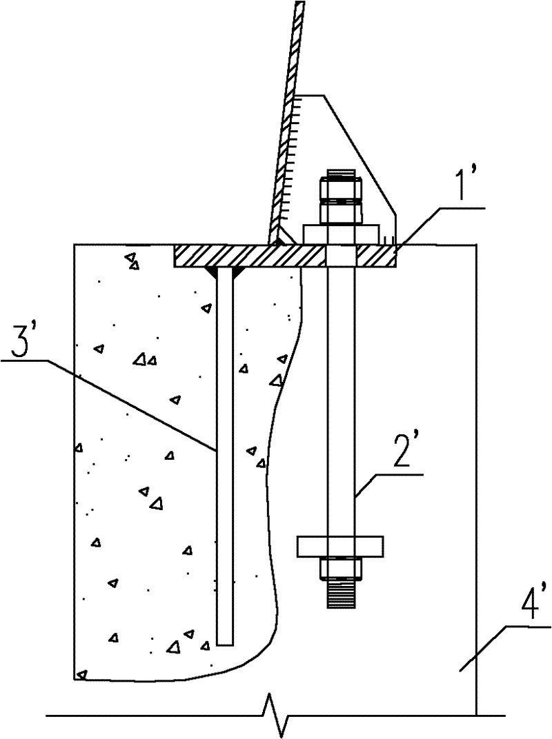
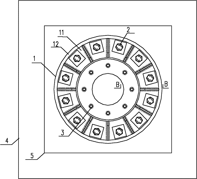
[0024] According to an embodiment of the present invention, as image 3 as well as Figure 4 As shown, the column base node of the frame column includes a bearing seat 5 set higher than the base 4, and it also includes a flange 1, and the flange 1 includes upper flange pieces 11 that are stacked and fixedly connected to each other and The lower flange piece 12 is fixed to the top of the bearing seat 5, and the upper flange piece 11 is fixed to the bottom of the frame column.

[0025] In a specific implementation process, the base 4 can be a concrete base 4, the bearing seat 5 is integrally formed with the base 4, and the bearing base 5 is higher than the top surface of the base 4 by a certain amount. In a preferred embodiment of the present invention, the area of ​​the cross-section of the bearing seat 5 is smaller than the area of ​​the top surface of the base 4, and the cross-section of the bearing seat 5 is a regular quadrilateral whose side length is greater than The out...


PUM


Abstract

The invention discloses a stylobate joint of a framework column, which comprises an anchor bolt and a shear reinforcement, and is characterized by further comprising a flange, wherein the flange comprises an upper flange piece and a lower flange piece which are stacked and fixedly connected with each other, the lower flange piece is fixed with the top of a base, and the upper flange piece is fixed with the bottom of the framework column. During the construction of the stylobate joint disclosed by the invention, the lower flange piece which is welded with the tension anchor bolt and the shear reinforcement is cast in the top part of the base in advance, and is poured with concrete together with the base of the previous stage, after the concrete of the base reaches the requirement of the design strength, an upper framework column with the stylobate joint is hoisted in place, the anchor bolt is screwed, the periphery of the upper flange piece is welded with the upper surface of the lowerflange piece through fillet welds, so a framework can be hoisted and permanently fixed at once, the subsequent wire stretching and erection can be instantly carried out, and both the construction efficiency and safety are improved.

Description

technical field [0001] The invention relates to a column foot of a steel structure, in particular to a column foot node of a frame column capable of improving construction efficiency and construction safety. Background technique [0002] The column base node of the frame column is the link to realize the internal force transmission between the superstructure and the foundation, and its performance and quality are very important for the entire project. The form of column feet can be simply divided into hinged type and rigid jointed type according to their force transmission characteristics. The former only transmits axial force and shear force, while the latter can also transmit the bending moment from the column body. The shaped column foot can provide rigid restraint to the column body and reduce the lateral deformation of the column body under the action of axial force. In the current substation steel frame design, due to the advantages of the rigid-joint column foot comp...

Claims


Application Information

Patent Timeline
Patent Type & Authority Patents(China)
IPC IPC(8): E04B1/38E04B1/41E04C3/30
Inventor 姜波许菁
Owner SHANGHAI ELECTRIC POWER DESIGN INST
Why Eureka
Try Eureka