Locating method of central precise grid of vacuum laser facula

A technology of laser spot and positioning method, which is applied to measurement devices, instruments, surveying and mapping, and navigation, etc., can solve problems such as large errors, and achieve the effects of reducing observation errors, improving observation accuracy, and ensuring continuity.

Active Publication Date: 2011-05-25
CHINA WATER NORTHEASTERN INVESTIGATION DESIGN & RES
View PDF3 Cites 11 Cited by
  • Summary
  • Abstract
  • Description
  • Claims
  • Application Information

AI Technical Summary

Problems solved by technology

[0005] The invention provides a precise grid positioning method for the vacuum laser spot center to solve the problem of large errors in monitoring

Method used


Image

  • Locating method of central precise grid of vacuum laser facula
  • Locating method of central precise grid of vacuum laser facula
  • Locating method of central precise grid of vacuum laser facula

Examples


Embodiment Construction

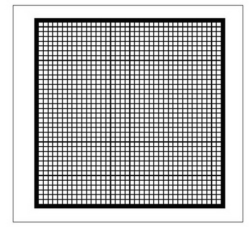
[0036] (1) Install a precision grid positioning screen at the receiving end. The coordinate origin of the receiving end is set at the lower left corner of the grid of the positioning screen. The positioning screen does not move with the camera. When adjusting and replacing the camera, just adjust the panorama of the screen to the effective shooting range of the camera The precise grid positioning screen is composed of several equally spaced squares and thickened borders, such as figure 1 As shown, the precision grid positioning screen cooperates with a set of automatically controlled motor-driven brackets to realize the closing and opening of the automatic control screen; the specific data acquisition and control process is as follows:

[0037] (1) Under the control of the computer, send the closing command of the precise grid positioning curtain to the controller at the receiving end, and the controller at the receiving end drives the motor to complete the closing of the preci...


PUM


Abstract

The invention relates to a locating method of central precise grid of vacuum laser facula, belonging to the field of building displacement monitor. A precise grid locating curtain is arranged at a receiving end; the origin of coordinates of the receiving end is arranged at the left lower corner of a locating curtain grid; the locating curtain does not move along with the camera; according to the position of the known real width of the precise grid and the central pixel coordinate of facula in some grid, the grid adopts a computer image calculating method for calculating the real coordinate of facula centre. The precise grid is used for determining the relationship between the camera pixel coordinate and the grid coordinate, thereby decreasing the generated observing error of nonlinear aberration of the camera shot, being capable of calculating the real change of central position of facula precisely, and greatly increasing the observing precision of the system.

Description

technical field [0001] The invention belongs to the field of building displacement monitoring. Background technique [0002] The domestic vacuum laser alignment displacement monitoring system has been widely used in the horizontal and vertical displacement monitoring of linear buildings. The common form is to set a point light source at the transmitting end, set a Fresnel half-wave zone plate, that is, a zone plate at the measuring point, and set an imaging and image acquisition device at the receiving end. Under the control of the computer, they enter the optical path respectively, and form a light spot at the receiving end, and monitor the displacement of the measuring point by calculating the displacement change of the center of the light spot. [0003] At present, there are mainly two control methods for spot image acquisition and center calculation of domestic similar products: one is to use the lower left corner of the image captured by the camera as the origin of the...

Claims


Application Information

Patent Timeline
Patent Type & Authority Applications(China)
IPC IPC(8): G01C11/00G01C11/12
Inventor 金正浩苏加林苑润保王德库王科峰范宝山徐岩彬孟中李克绵李俊富姜盛吉徐小武
Owner CHINA WATER NORTHEASTERN INVESTIGATION DESIGN & RES
Why Eureka
Try Eureka