
Memory total ionizing dose experimenting clamp, and experimenting and testing method thereof

A technology of total dose effect and test fixture, applied in the direction of static memory, instrument, etc., can solve the problems of the most severe, unsystematic sorting, and the difference in the evaluation results of the device's ability to resist space radiation.

Active Publication Date: 2011-05-25
BEIJING SHENGTAOPING TEST ENG TECH RES INST
View PDF0 Cites 10 Cited by
  • Summary
  • Abstract
  • Description
  • Claims
  • Application Information

AI Technical Summary

Problems solved by technology

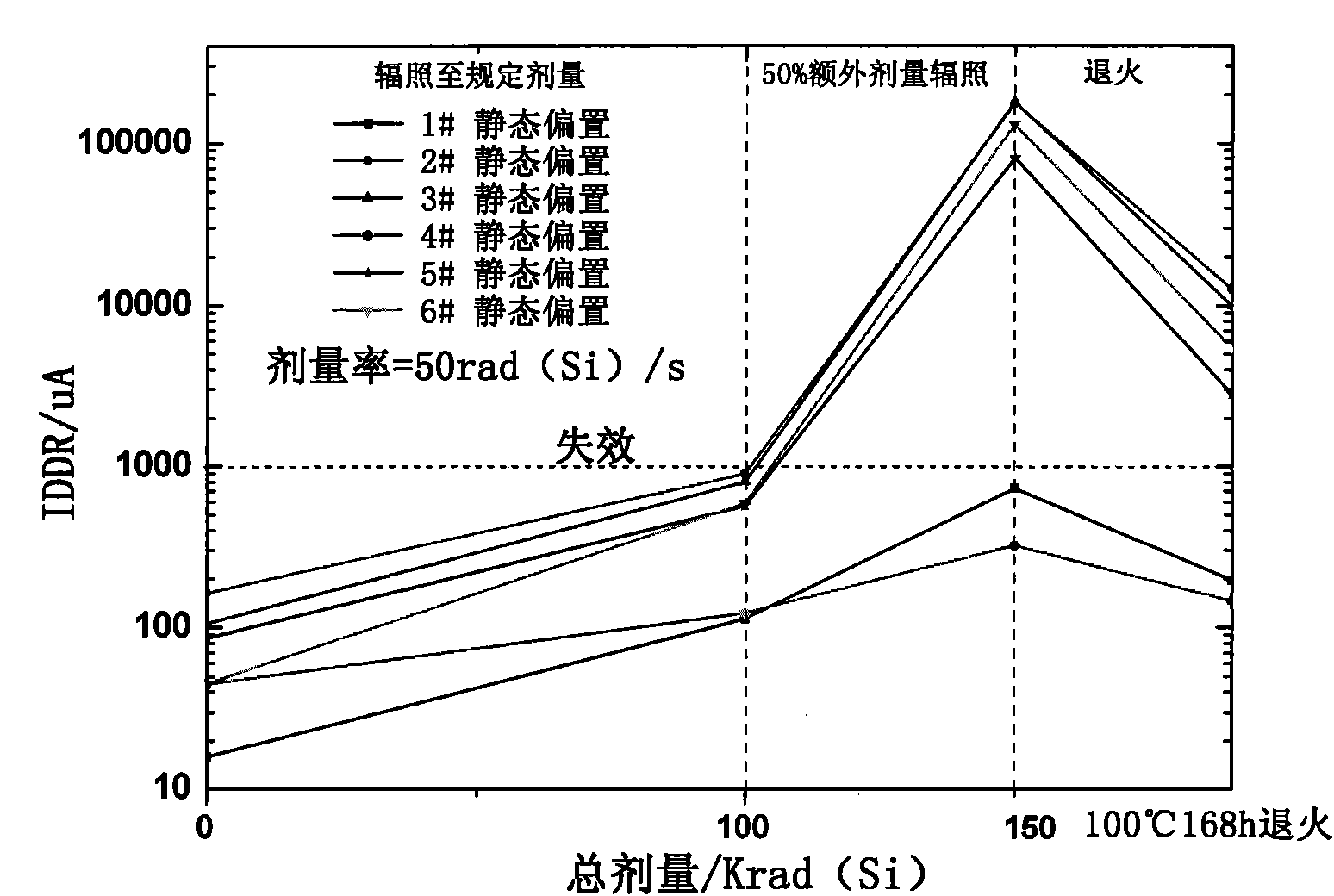
[0005] 1. GJB 548B method 1019.2, GJB 5422-2005 "Measurement method for radiation cumulative dose effect of military electronic components", ESA / SCC 22900 "Guidelines for steady-state radiation ionization (TID) total dose test method", ASTM F1892 "Steady total Dose Test Method Guide", MIL-STD-883G "Microelectronic Device Test Methods and Procedures" and other domestic and foreign steady-state total dose effect test methods and standards are not completely consistent; the bias of the device in the domestic and foreign steady-state total dose effect The regulations are vague, and the standard stipulates that the device should be under the worst bias condition; the standard has many selection conditions for the dose rate during the irradiation of the device, and there is no provision for the test sequence of the memory after irradiation; for the high temperature accelerated annealing test program The understanding is not very accurate; these all lead to large differences in the evaluation results of the space radiation resistance of the device;
[0006]2. The design of the memory steady-state total dose test fixture is relatively complicated, and no systematic arrangement has been carried out at present

Method used


Image

  • Memory total ionizing dose experimenting clamp, and experimenting and testing method thereof
  • Memory total ionizing dose experimenting clamp, and experimenting and testing method thereof
  • Memory total ionizing dose experimenting clamp, and experimenting and testing method thereof

Examples


Embodiment Construction

[0041] A memory steady-state total dose effect test fixture, test and test method proposed by the present invention are described as follows with reference to the accompanying drawings.

[0042] The hardware design of the memory steady-state total dose test fixture is as follows: figure 1 shown, includes: test board, carrier board and computer. The test board is used to monitor the current of the memory under test and the change of its data value, and transmit the information to the computer; the computer is used to process and display the information from the test board; The memory under test is in an electrical connection state, and the memory under test communicates with the test board.

[0043] The test board includes a development board and a function expansion board based on Atmega64 single-chip microcomputer. Atmega64 single-chip microcomputer is the main control chip. Atmega64 is an 8-bit AVR single-chip microcomputer with a performance of up to 16MIPS when working at...


PUM


Abstract

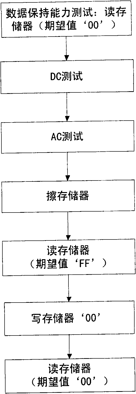
The invention discloses a memory total ionizing dose experimenting clamp. The clamp comprises a testing board, a carrying board and a computer, wherein the testing board is used for monitoring changes of current of a tested memory and data values thereof, and transmitting information to the computer; the carrying board is used for placing the tested memory, and providing an interface to ensure that the tested memory is communicated with the testing board; and the computer is used for processing and displaying the information transmitted from the testing board. The memory total ionizing dose experimenting and testing method determines the testing condition of the memory total ionizing dose, and comprises the following steps of: determining the offset condition when the memory is irradiated, selecting the dose rate during irradiation, carrying out 50% extra irradiation and high-temperature accelerated annealing test and determining electric parameter testing sequence after memory irradiation. The experimenting clamp and the experimenting and testing method improve scientificalness and accuracy of the memory total ionizing dose testing result.

Description

technical field [0001] The invention relates to the technical field of a large-scale integrated circuit total dose effect test method, in particular to the design of a memory steady-state total dose effect fixture, and its test and test method. Background technique [0002] Charged particles and electrons in the space radiation environment produce ionized total dose effects in memory, which seriously threatens the reliability and safety of star memory. In the past, people's research on memory circuits was mainly aimed at the study of single event effects, and there are many domestic and foreign reports on this aspect. However, there are relatively few literature reports on the study of the total dose effect of memory circuits. The total dose effect test is one of the important radiation tests. In the verification test, the satellite memory circuit needs to undergo a total dose effect test to evaluate the space radiation resistance of the memory. [0003] With the impact of...

Claims


Application Information

Patent Timeline
Patent Type & Authority Applications(China)
IPC IPC(8): G11C29/00
Inventor 王群勇阳辉陈冬梅钟征宇姜大勇陈宇刘燕芳白桦
Owner BEIJING SHENGTAOPING TEST ENG TECH RES INST
Learn More