Over-temperature protection circuit for radio frequency power amplifier

An over-temperature protection circuit and radio frequency power technology, which is applied to the layout of the amplifier protection circuit, improving the amplifier to reduce temperature/power voltage changes, etc., can solve the problems of current collapse, tube burnout, device burnout, etc., and achieve simple structure and avoid leakage. current, the effect of easy integration

Active Publication Date: 2011-05-25
北京昂瑞微电子技术股份有限公司
View PDF3 Cites 18 Cited by
  • Summary
  • Abstract
  • Description
  • Claims
  • Application Information

AI Technical Summary

Problems solved by technology

In order to obtain the output power and efficiency required by various communication standards, the emitter area of ​​the output tube T3 is very large, and generally adopts a multi-finger structure. Due to the large output power and current, it is easy to cause temperature differences between fingers, resulting in Current collapse and other problems lead to burnout of the device; on the other hand, due to some external factors, such as high power supply voltage and serious load mismatch, etc., due to the insufficient thermal stability of the RF power amplifier, it is easy to overheat itself due to excessive current. burn the pipe

Method used


Image

  • Over-temperature protection circuit for radio frequency power amplifier
  • Over-temperature protection circuit for radio frequency power amplifier
  • Over-temperature protection circuit for radio frequency power amplifier

Examples


Embodiment Construction

[0025] In order to facilitate the understanding of those skilled in the art, the present invention will be further described in detail below in conjunction with the accompanying drawings and embodiments.

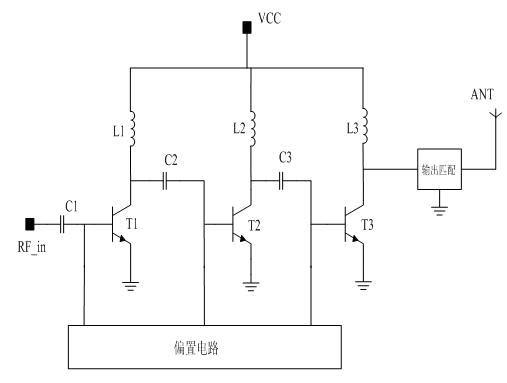
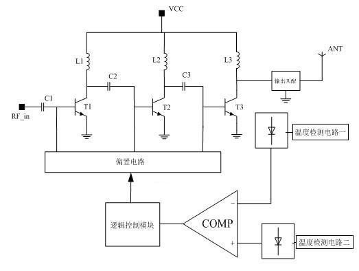
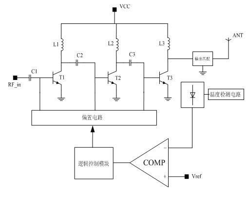
[0026] figure 2 Shown is a block diagram of the principle of the present invention, and the disclosed over-temperature protection circuit includes a temperature detection circuit, a comparator circuit (COMP), a logic control circuit and a bias circuit connected in sequence; the temperature detection circuit detects the chip temperature of the radio frequency power amplifier Then output to the comparator circuit, the comparator circuit outputs the trigger signal to the logic control circuit, and the logic control circuit controls the bias circuit to adjust the working current of the radio frequency power amplifier and then adjust the working temperature to realize protection. In the figure, RF_in is the radio frequency input signal, and VCC is the power supply voltage.

[0...


PUM


Abstract

The invention relates to an over-temperature protection circuit for a radio frequency power amplifier. The circuit comprises a temperature detection circuit, a comparator circuit, a logic control circuit and a bias circuit which are connected in turn, wherein the temperature detection circuit detects the temperature of a chip and outputs the temperature to the comparator circuit, the comparator circuit outputs a trigger signal to the logic control circuit, and the logic control circuit controls the bias circuit to adjust the current of the amplifier to adjust the working temperature of the logic control circuit so as to realize protection; reference voltage is input into one end of a comparator in the comparator circuit, and the output signal of the temperature detection circuit is input into the other end of the comparator; or the output signal of the temperature detection circuit is input into the two input ends; and the temperature detection circuit consists of one or more diodes which are connected in series. When mobile communication equipment does not work, the over-temperature protection circuit can be switched off in a bias circuit control mode, and leakage current in the over-temperature protection circuit is avoided so as not to cause unnecessary energy loss; and the circuit is flexibly applied and convenient to integrate.

Description

technical field [0001] The invention relates to the technical field of radio frequency power amplifiers, in particular to an overtemperature protection circuit for radio frequency power amplifiers. Background technique [0002] As the core device in the wireless communication system, the radio frequency power amplifier (PA) should work normally in various harsh environments, such as working under severe load mismatch, high power supply voltage and high power level for a long time. All conditions will cause the current of the RF power amplifier to increase rapidly, thereby generating a lot of heat. The RF power amplifier is not good enough for heat dissipation and thermal protection, and it is easy to cause the tube to fail due to thermal breakdown. In order to avoid the problem of overheating, burning and breakdown of the RF power amplifier tube caused by the harsh surrounding environment or the unsatisfactory heat dissipation and load matching of the communication equipment...

Claims


Application Information

Patent Timeline
Patent Type & Authority Applications(China)
IPC IPC(8): H03F1/52
CPCH03F1/30H03F1/52
Inventor 彭凤雄张旭光
Owner 北京昂瑞微电子技术股份有限公司
Why Eureka
Try Eureka