Tower crane lifting hook video monitoring device with energy-saving and doubling functions and monitoring method

A video monitoring and tower crane technology, applied in the video field, can solve problems such as poor operation performance and poor system operability, and achieve the effect of simplifying operation procedures, preventing cables from being crushed, and achieving good video effects

Inactive Publication Date: 2011-05-25
XIAN UNIV OF TECH
View PDF5 Cites 10 Cited by
  • Summary
  • Abstract
  • Description
  • Claims
  • Application Information

AI Technical Summary

Problems solved by technology

[0004] The purpose of the present invention is to provide a tower crane hook video monitoring device with energy-saving and variable zoom functions, which solves the problems of the existing tower crane video monitoring system in power supply, signal transmission, lens magnification control and poor system operability.
[0005] Another object of the present invention is to provide a video monitoring method for tower crane hooks using the above-mentioned device to solve the problems of poor operability in energy saving and zoom function in the prior art

Method used


Image

  • Tower crane lifting hook video monitoring device with energy-saving and doubling functions and monitoring method
  • Tower crane lifting hook video monitoring device with energy-saving and doubling functions and monitoring method
  • Tower crane lifting hook video monitoring device with energy-saving and doubling functions and monitoring method

Examples


Embodiment Construction

[0023] The present invention will be described in detail below in conjunction with the accompanying drawings and specific embodiments.

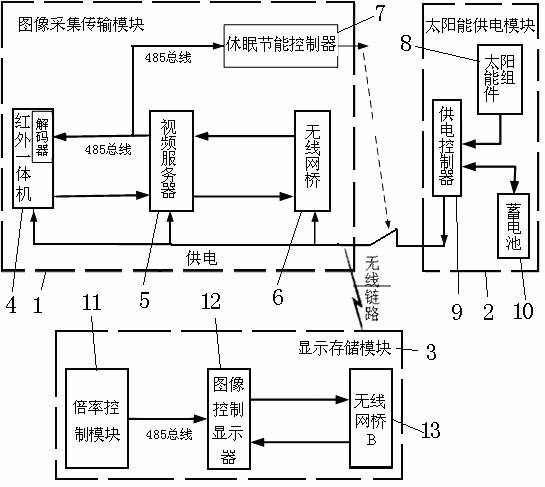
[0024] Such as figure 1 , is the structural block diagram of the device of the present invention. The hardware part of the device of the present invention consists of three major modules, namely the image acquisition and transmission module 1 and the solar power supply module 2 arranged on the luffing trolley of the tower crane, and the display and storage module arranged in the cab 3.

[0025] The image acquisition and transmission module 1 includes an infrared all-in-one machine 4 (comprising a camera, a decoder, and an infrared light connection), a video server 5 and a wireless network bridge 6 connected in sequence, and the infrared all-in-one machine 4 and video server 5 are simultaneously connected to a dormant energy-saving controller 7 .

[0026] The solar power supply module 2 is used for solar power supply control, including a pow...


PUM


Abstract

The invention discloses a tower crane lifting hook video monitoring device with energy-saving and doubling functions, which comprises an image collecting and transmitting module, a solar power supply module and a display memory module, wherein the image collecting and transmitting module and the solar power supply module are arranged on an amplitude-change trolley of a tower crane, the display memory module is arranged in a cab, the image collecting and transmitting module comprises an infrared all-in-one machine, a video sever and a wireless network bridge which are sequentially connected, the infrared all-in-one machine and the video server are simultaneously connected with a dormancy energy-saving controller, the solar power supply module comprises a power supply controller which is respectively connected with a solar assembly and a storage battery, the power supply controller is respectively connected with the infrared all-in-one machine, the video server, the wireless network bridge and the dormancy energy-saving controller, the display memory module comprises a multiplying power control module, an image control display and a wireless network bridge B, and the multiplying power control module is connected with a pedal unit. The invention also discloses a lifting video monitoring method using the tower crane lifting hook video monitoring device, and the remote control on the camera lens magnification and the dormancy and energy-saving functions are realized through a pedal module.

Description

technical field [0001] The invention belongs to the field of video technology, and relates to a video monitoring device for a tower crane hook with energy-saving and variable-magnification functions, and also relates to a video monitoring method for a tower crane hook using the device. Background technique [0002] Tower cranes (hereinafter referred to as tower cranes) belong to high-altitude operation equipment. The operating room is located at the top of the tower crane. During the working process, tower crane operators often cannot see the ground conditions clearly. In order for the tower crane to complete the required operations, ground commanders are generally required Cooperate with the tower crane operator, and the tower crane operator operates the crane according to the instructions of the commander. In this way of working, on the one hand, if the commanders have a weak sense of responsibility and insufficient personal ability, safety accidents are likely to occur; ...

Claims


Application Information

Patent Timeline
Patent Type & Authority Applications(China)
IPC IPC(8): H04N7/18B66C13/16
CPCY02B60/50
Inventor 杨静
Owner XIAN UNIV OF TECH
Why Eureka
Try Eureka