High-frequency high-sensitivity ultrasonic sensor

A high-sensitivity, ultrasonic technology, applied in the direction of piezoelectric/electrostrictive transducer microphones, etc., can solve the problems of piezoelectric ceramic sheet crack damage, product life shortening, test accuracy less than 3mm, etc.

Active Publication Date: 2011-05-25
BESTAR HLDG
View PDF6 Cites 11 Cited by
  • Summary
  • Abstract
  • Description
  • Claims
  • Application Information

AI Technical Summary

Problems solved by technology

[0003] With the advancement of science and technology, the development of the ultrasonic sensor industry is advancing by leaps and bounds. The traditional ultrasonic sensors within 100KHz mainly include sensors with lower frequencies such as 40KHz, 48KHz, and 58KHz. ; The resolution, test accuracy and frequency of piezoelectric ceramic ultrasonic sensors are directly related to the frequency. , liquid level gauge, etc., its application field is more and more extensive, the traditional high-frequency ultrasonic sensor directly bonds the piezoelectric ceramic sheet to the matching layer, and then puts the entire connecting body into a shell with an inner cavity, which is There are two problems in this sensor: 1. Due to the lack of resonant coupling medium, its product has low sensitivity and low emission sound pressure;
[0004] 2. Due to the lack of dielectric matching coupling and resonance design, in order to obtain higher sensitivity, the only way to increase the driving voltage of the piezoelectric ceramic is to increase the driving voltage of the piezoelectric ceramic, and work under conditions close to the limit value for a long time, the piezoelectric ceramic will appear crack damage and the product shortened lifespan

Method used


Image

  • High-frequency high-sensitivity ultrasonic sensor
  • High-frequency high-sensitivity ultrasonic sensor
  • High-frequency high-sensitivity ultrasonic sensor

Examples


Embodiment Construction

[0026] The present invention will be further described below in conjunction with the accompanying drawings and specific embodiments.

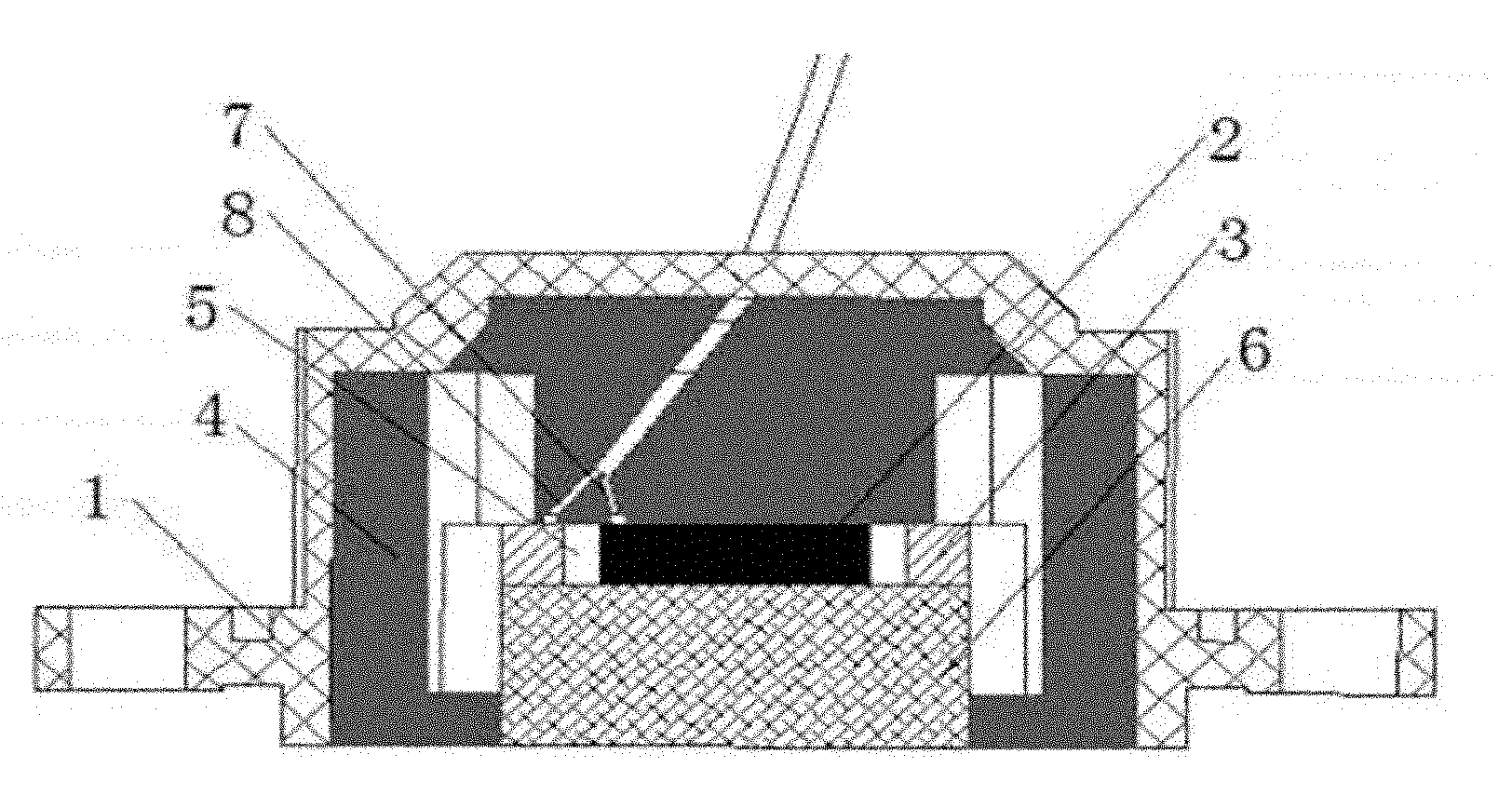
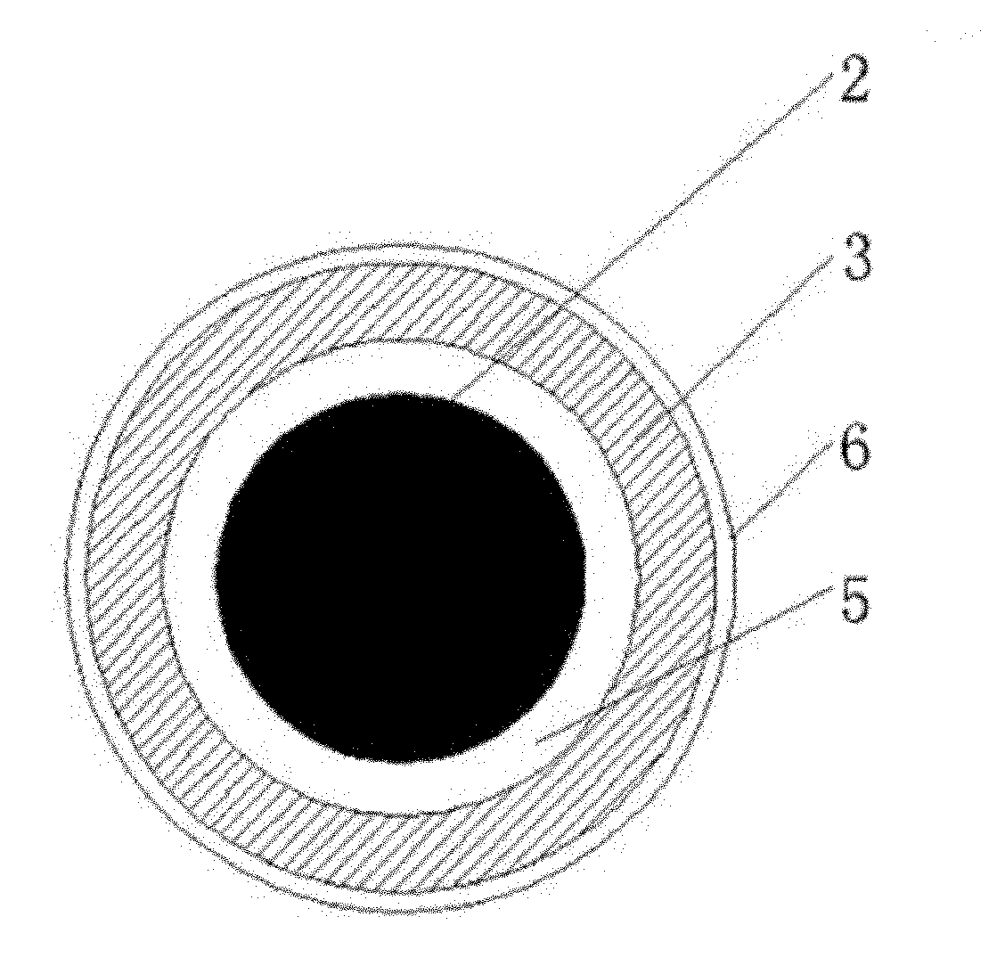
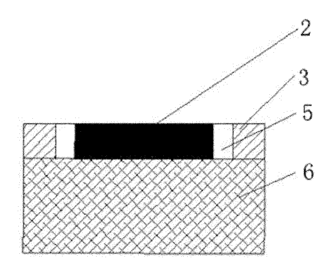
[0027] see figure 1 , 2 . As shown in 3, a high-frequency and high-sensitivity ultrasonic sensor includes a hollow plastic shell 1 with one end open and one end closed, a piezoelectric ceramic sheet 2 arranged in the hollow plastic shell 1 and the lower end of the piezoelectric ceramic sheet 2 The matching layer 6 connected face to face, and the shielding material 4 filled in the hollow plastic shell, the piezoelectric ceramic sheet is provided with a metal ring 3, the upper end surface of the metal ring 3 is closely matched with the inner wall of the plastic shell 1, and the lower end surface Fitting closely with the upper end surface of the matching layer 6, the piezoelectric ceramic sheet 2 is located in the metal ring 3, and the resonant cavity 5 is formed between the outer peripheral surface of the piezoelectric ceramic sheet 2 and the in...


PUM


Abstract

The invention relates to a high-frequency high-sensitivity ultrasonic sensor applied in the fields of robot induction, proximity switches, industrial high-precision automation, liquid level measurement, human height test, hopper charge test, smog detectors and the like. The sensor comprises a hollow plastic shell with one open end and the other closed end, a piezoelectric ceramic plate arranged in the hollow plastic shell, a matching layer connected with the lower end face of the piezoelectric ceramic plate, and a shielding material filled in the hollow plastic shell; the upper end face of the matching layer is provided with a metal ring around the piezoelectric ceramic plate; a resonant cavity is formed by the distance between the metal ring and the piezoelectric ceramic plate; and the cathode of the piezoelectric ceramic plate is electrically connected with the metal ring, the anode of an external connecting terminal is electrically connected with the anode of the piezoelectric ceramic plate, and the cathode of the external connecting terminal is electrically connected with the metal ring. The sensor has the advantages of low driving voltage, high sensitivity and long service life.

Description

technical field [0001] The invention relates to a high-frequency and high-sensitivity ultrasonic sensor used in the fields of robot induction, proximity switch, industrial high-precision automation, liquid level measurement, human body height test, hopper loading test, smoke detector and the like. Background technique [0002] Piezoelectric ceramic ultrasonic distance measurement is to make the sensor emit ultrasonic waves by giving pulse driving voltage to the sensor. When an obstacle is encountered, the reflected wave acts on the sensor. By calculating the product of the time difference between the sensor’s emission and reception and the propagation speed, the distance is calculated. distance. [0003] With the advancement of science and technology, the development of the ultrasonic sensor industry is advancing by leaps and bounds. The traditional ultrasonic sensors within 100KHz mainly include sensors with lower frequencies such as 40KHz, 48KHz, and 58KHz. ; The resoluti...

Claims


Application Information

Patent Timeline
Patent Type & Authority Applications(China)
IPC IPC(8): H04R17/02
Inventor 邹东平
Owner BESTAR HLDG
Why Eureka
Try Eureka