
Corn rootstalk soil removal machine

A technology for removing soil and stubble, which is applied in the fields of collectors, agricultural machinery and implements, agriculture, etc., can solve the problem that corn stubble is not effectively utilized, the quality of stubble chopping and burial is not high, and the next stubble seeds are affected. Implantation and other problems, to achieve the effect of good root-soil separation, novel structural design, and reduced processing costs

Inactive Publication Date: 2012-05-02
JILIN UNIV
View PDF0 Cites 0 Cited by
  • Summary
  • Abstract
  • Description
  • Claims
  • Application Information

AI Technical Summary

Problems solved by technology

Manual stubble planing is not only labor-intensive, time-consuming and labor-intensive, but also takes away part of the fertilizer in the soil, resulting in soil compaction; the root stubble is broken and returned to the field with a rotary tiller, the root stubble is difficult to cut, and it is easy to wind the knife shaft. Moreover, the quality of chopping and burying the stubble is not high, and the stubble left in the ground often affects the implantation of the next stubble seed and affects the quality of follow-up operations, so the corn stubble is not effectively utilized.
At present, the biomass energy utilization of corn stubble is still in its infancy, and the research on corn stubble remover is almost blank. This paper innovatively proposes a corn stubble remover with good root-soil separation effect. The development and utilization of renewable biomass energy has important practical significance

Method used


Image

  • Corn rootstalk soil removal machine
  • Corn rootstalk soil removal machine
  • Corn rootstalk soil removal machine

Examples


Embodiment Construction

[0021]The present invention is described in detail below in conjunction with accompanying drawing:

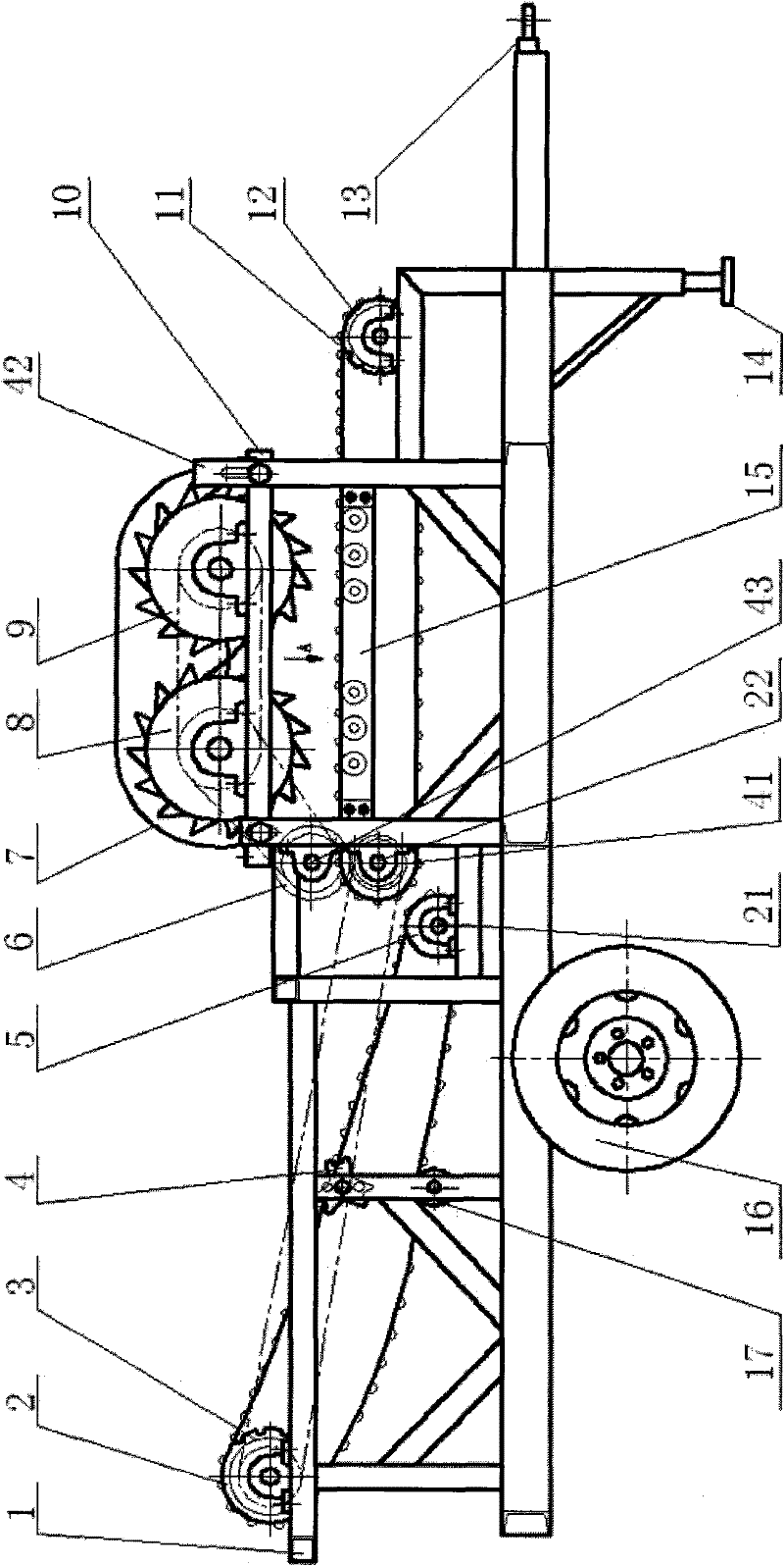
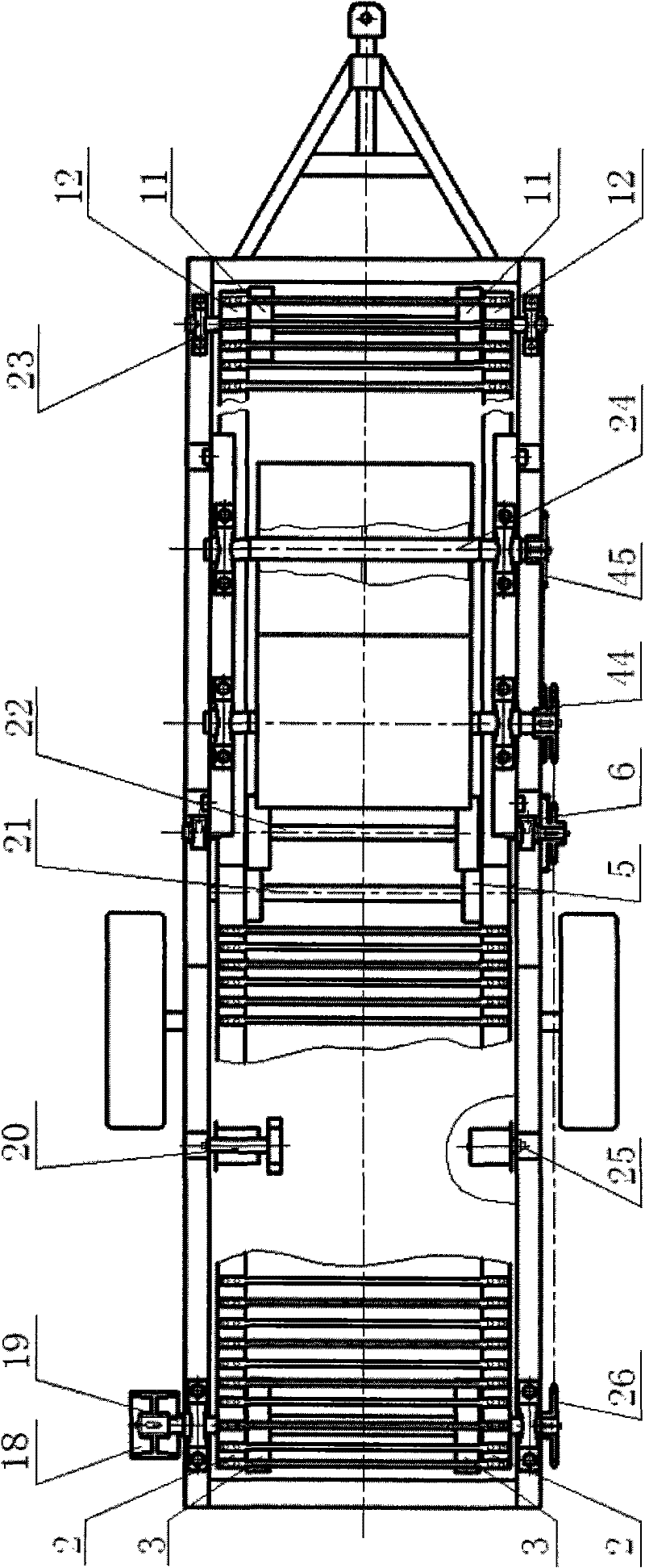
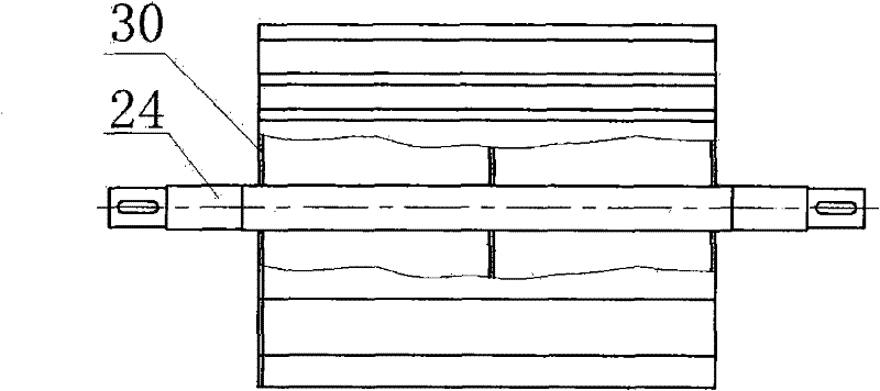
[0022] refer to figure 1 and figure 2 , is the first implementation technical scheme of the corn stubble remover, and the corn stubble remover includes a frame 1, a traction device 13, a double-roller crushing device, and a belt-type bar chain conveying and feeding mechanism , Rod chain vibration separation mechanism, road wheel mechanism and transmission system.

[0023] The frame 1 is a three-dimensional frame structure, which is composed of a main longitudinal beam frame and an auxiliary frame.

[0024] The main longitudinal beam frame is the carrier of the main mechanisms of the corn stubble remover. The main longitudinal beam frame is a planar frame structure made of two main longitudinal beams made of profiled tubular steel and several small beams made of profiled tubular steel through welding, riveting or / and bolting.

[0025] The auxiliary frame is the carrier of t...


PUM


Abstract

The invention discloses a corn rootstalk soil removal machine. The machine comprises a frame, a double-drum rolling and breaking device, a belt open link chain conveying and feeding mechanism, an open link chain dithering and separating mechanism and a drive system, wherein, the double-drum rolling and breaking device comprises a rear rolling drum, a front rolling drum, two angle iron supports, two roller supports, four channel steel upright columns and six support rollers; the double-drum rolling and breaking device is arranged on the right end of the frame; the open link chain dithering andseparating mechanism is arranged on the left end of the frame; the belt open link chain conveying and feeding mechanism is arranged below the rear rolling drum and the front rolling drum; the drive system connects corresponding parts together through a chain wheel, a gear and a chain; the front rolling drum and the rear rolling drum are arranged between the two angle iron supports to form rotary connection; two ends of the two angle iron supports are fixedly connected with the four channel steel upright columns; the six support rollers are arranged between the two roller supports to form rotary connection; and the vertical distance from the vertex of rolling teeth to the six support rollers is 50-70mm.

Description

technical field [0001] The invention relates to a crop desoiling machine in the field of agricultural machinery, more specifically, the invention relates to a corn stubble desoiling machine. Background technique [0002] At present, there are two main ways to deal with the stubble: one is to manually dig the stubble, pile it up or collect it and burn it; the other is to use a rotary tiller to crush the stubble and return it to the field. Manual stubble planing is not only labor-intensive, time-consuming and labor-intensive, but also takes away part of the fertilizer in the soil, resulting in soil compaction; the root stubble is broken and returned to the field with a rotary tiller, the root stubble is difficult to cut, and it is easy to wind the knife shaft. And the quality of chopping and burying the root stubble is not high, and the stubble left in the ground often affects the implantation of the next stubble seed and affects the quality of follow-up operations, so the cor...

Claims


Application Information

Patent Timeline
Patent Type & Authority Patents(China)
IPC IPC(8): A01B43/00
Inventor 贾庆祥杨新义王继利张富
Owner JILIN UNIV
Learn More