Tomato harvesting and separating device and tomato harvester using same

A separation device and harvester technology, applied in harvesters, agricultural machinery and implements, applications, etc., can solve the problems of low vibration frequency, low reliability, complex structure, etc., and achieve high vibration frequency, reliable operation, and small power loss. Effect

Inactive Publication Date: 2011-06-01
SHIHEZI UNIVERSITY
View PDF5 Cites 6 Cited by
  • Summary
  • Abstract
  • Description
  • Claims
  • Application Information

AI Technical Summary

Problems solved by technology

The spring tooth roller realizes the vibration of the spring teeth of the spring tooth roller through two sets of swing mechanisms. The swing mechanism is composed of a driving wheel, a driven wheel, a transmission shaft and an eccentric block, and the swing is mainly realized by the vibration of the eccentric block when it rotates. The vibration of the transmission shaft of the mechanism is rotated, and then the transmission shaft of the swing mechanism causes the rotational inertia of the spring-toothed roller to stop and realize the vibration. The structure is complex, the vibration frequency is low and the power loss is serious, especially the reliability of long-term work is low.

Method used


Image

  • Tomato harvesting and separating device and tomato harvester using same
  • Tomato harvesting and separating device and tomato harvester using same
  • Tomato harvesting and separating device and tomato harvester using same

Examples


Embodiment 1

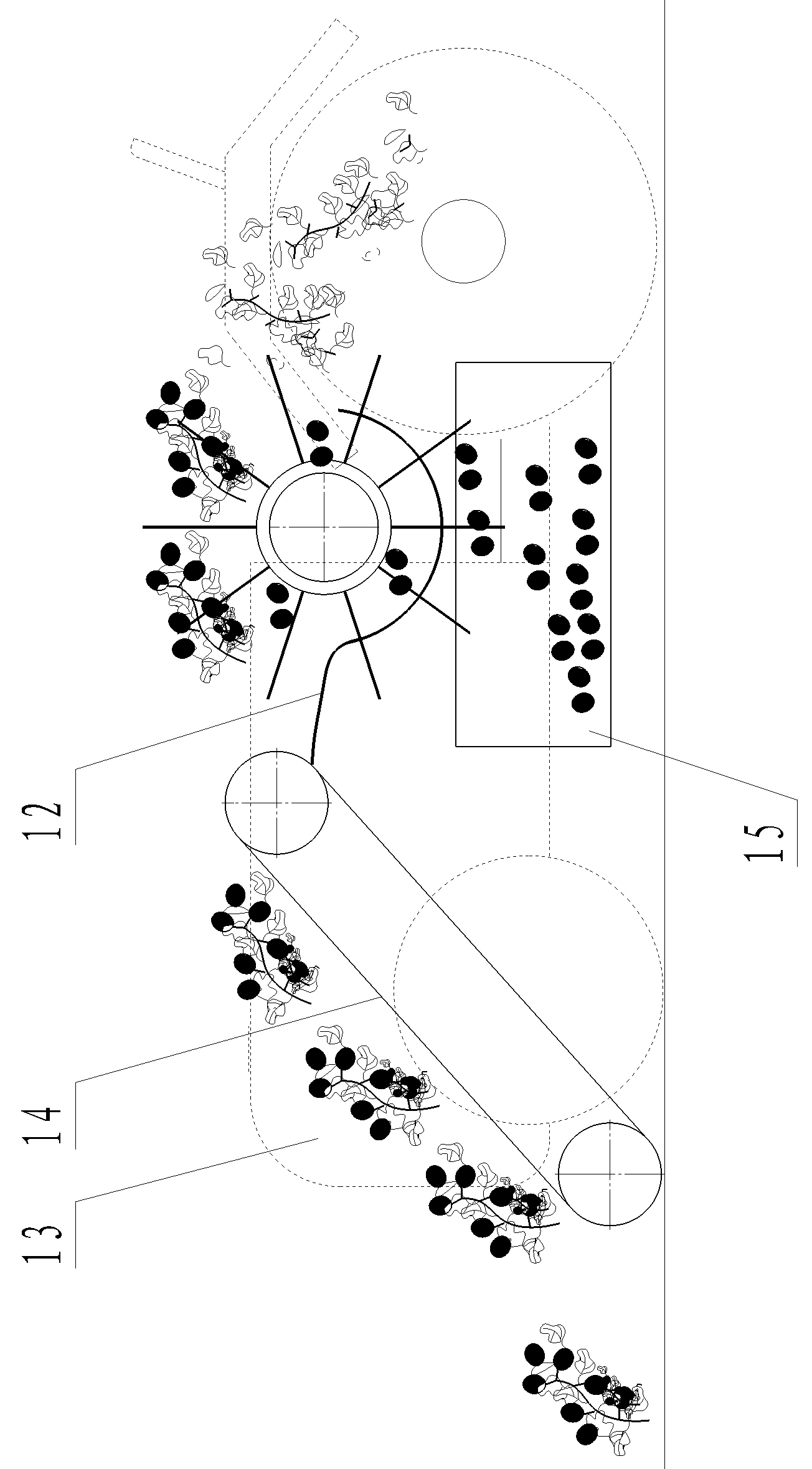
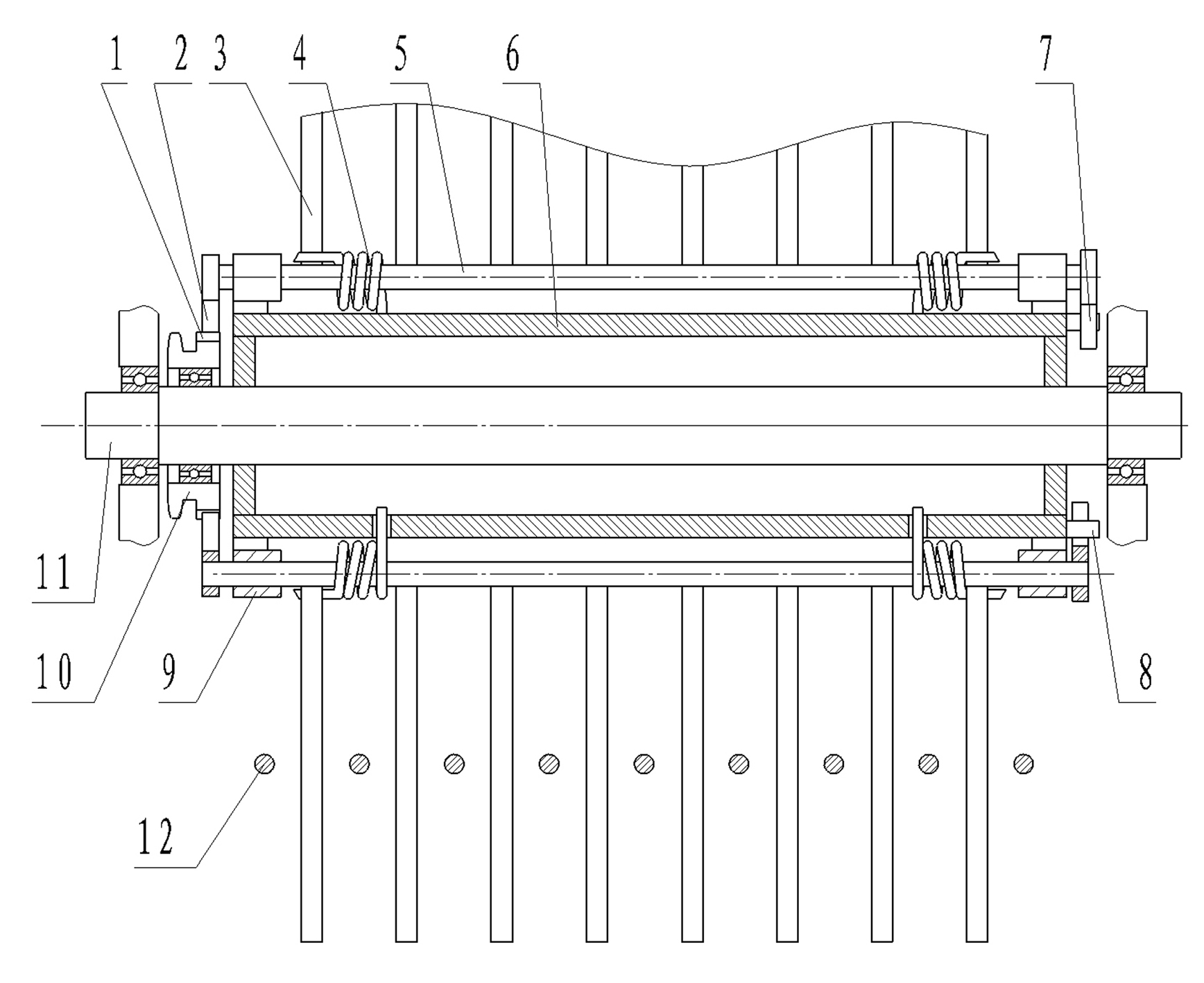
[0021] Embodiment 1: refer to Figure 1~Figure 3 , is a schematic structural diagram of the harvesting and separating device in Example 1 of the present invention. Comprising a grid screen 12 and a spring tooth cylinder 6, a spring tooth bar 5 is axially arranged on the circle of the spring tooth cylinder 6, and the spring teeth 3 arranged in a finger shape on the spring tooth bar 5 and the spring teeth 3 are arranged around the circle of the spring tooth cylinder 6 The top is radially radial, and the spring tooth rod 5 is connected to the spring tooth roller 6 through the bearing seat 9 and can rotate in the bearing seat 9. The spring tooth bar 5 is provided with a return spring 4 and a swing rod 2, and the return The spring 4 is a torsion spring, which is arranged on the spring tooth bar 5, and the swing bar 2 is arranged on one end of the spring tooth bar 5, and the end of the spring tooth roller 6 corresponding to the swing bar 2 is provided with a Elastic tooth cylinder ...

Embodiment 2

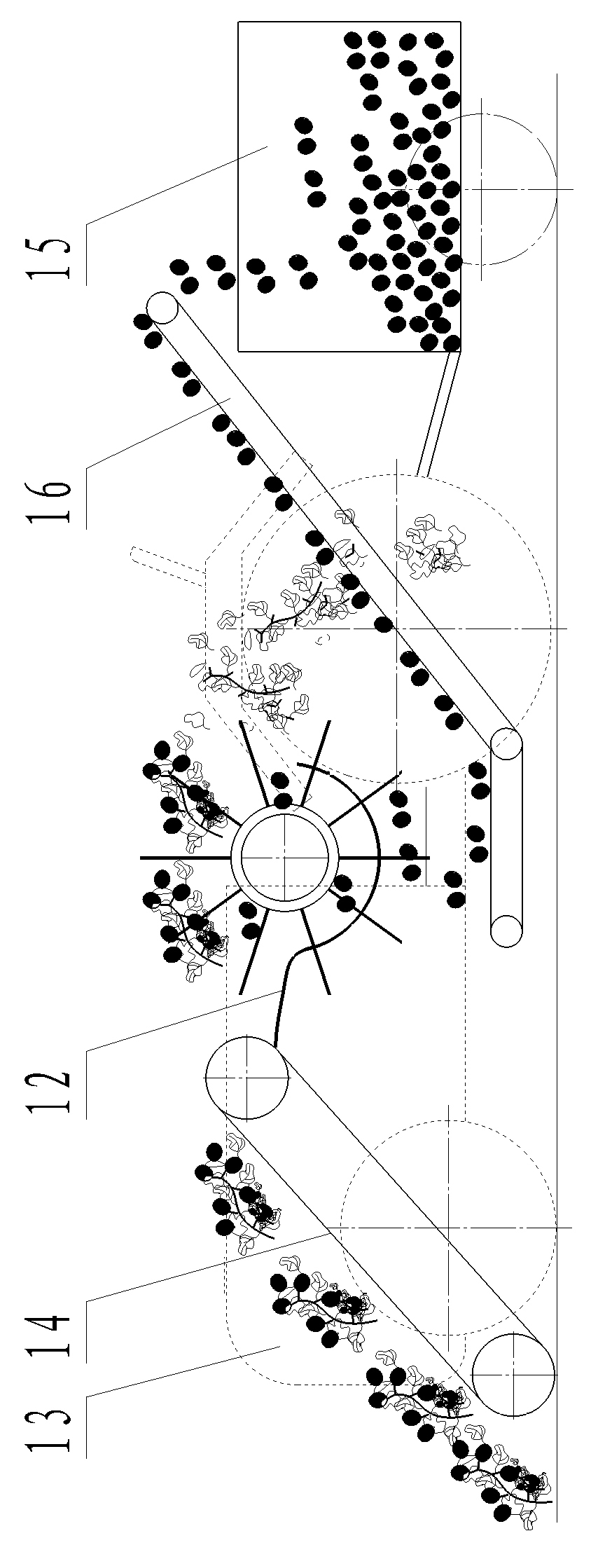
[0023] Embodiment 2: refer to Figure 4 , is a schematic structural diagram of the harvesting and separating device in Example 2 of the present invention. Compared with Embodiment 1, the difference of this embodiment is that the tooth-shaped protrusions 1 on one circumference of the vibrating cam 10 are arc-shaped protrusions.

Embodiment 3

[0024] Embodiment 3: refer to Figure 5 , is a schematic structural diagram of the harvesting and separating device in Example 5 of the present invention. Compared with Embodiment 1, the difference of this embodiment is that the return spring 4 is a tension spring, one end of the tension spring is connected to the limit rod 7 at the end of the spring tooth rod 5, and the other end is connected to the upper limit of the spring tooth roller 6. The gear bar 8 is connected. Extension spring among the present embodiment also can be replaced by compression spring.


PUM


Abstract

The invention discloses a tomato harvesting and separating device and a tomato harvester using the same. The tomato harvesting and separating device comprises a grid screen (12) and an elastic tooth roller (6), wherein an elastic tooth rod (5) is axially arranged on the circumference of the elastic tooth roller (6); elastic teeth (3), a return spring (4) and a swinging rod (2) are arranged on the elastic tooth rod (5); a vibrating and swinging cam (10) coaxial with the elastic tooth roller (6) is arranged at the end part of the elastic tooth roller (6) in the position corresponding to the swinging rod (2); and a tooth-shaped bulge (1) is arranged on the circumference of the vibrating and swinging cam (10), and the tooth-shaped bulge (1) is capable of ejecting the swinging rod (2) to enable the elastic tooth rod (5) to rotate in a bearing seat (9). Compared with the prior art, the separating device in the invention is simple in structure, high in vibrating frequency, adjustable in vibration amplitude, easy for controlling, good in vibrating effect, low in power loss and reliable in work.

Description

technical field [0001] The present invention relates to a kind of separation device and the crop harvesting machine that constitutes, specifically a kind of crop vine fruit separation device and the crop harvesting machine that constitutes by this device, especially a kind of tomato harvesting separation device and this device constitute tomato harvester. Background technique [0002] With the development of agricultural production technology, higher requirements have been put forward in terms of planting scale and efficiency. Especially in recent years, the planting area of ​​processing tomato, peanut and other crops has continuously expanded, and has become an important agricultural economic crop in our country. However, at present, the harvest of this type of crops in China mainly relies on manual labor, which seriously restricts the development of this type of economic crop industry. Therefore, mechanized planting, especially the replacement of manual harvesting by mech...

Claims


Application Information

Patent Timeline
Patent Type & Authority Applications(China)
IPC IPC(8): A01D45/00
Inventor 李盛林毕新胜朱荣光高广娣肖彬彬
Owner SHIHEZI UNIVERSITY
Why Eureka
Try Eureka