Device and method for measuring detonating velocity of explosive

A technology for measuring devices and explosives, applied in measuring devices, linear/angular velocity measurement, velocity/acceleration/impact measurement, etc., can solve the problems of differences, inability to reflect the actual detonation velocity of explosives and changes in detonation velocity, and achieve simple structure of the device, The measurement method is simple and practical, and the design is reasonable

Inactive Publication Date: 2011-06-01
XIAN TIANLI CLAD METAL MATERIALS
View PDF3 Cites 30 Cited by
  • Summary
  • Abstract
  • Description
  • Claims
  • Application Information

AI Technical Summary

Problems solved by technology

Moreover, the detonation velocity measured by these two methods is very different from the detonation velocity of the explosive in the process of detonation compounding, which cannot reflect the actual detonation velocity and the variation of the detonation velocity of the explosive in the process of detonation compounding, and is not suitable for the measurement of the detonation velocity of explosive compound explosives.

Method used


Image

  • Device and method for measuring detonating velocity of explosive
  • Device and method for measuring detonating velocity of explosive
  • Device and method for measuring detonating velocity of explosive

Examples


Embodiment 1

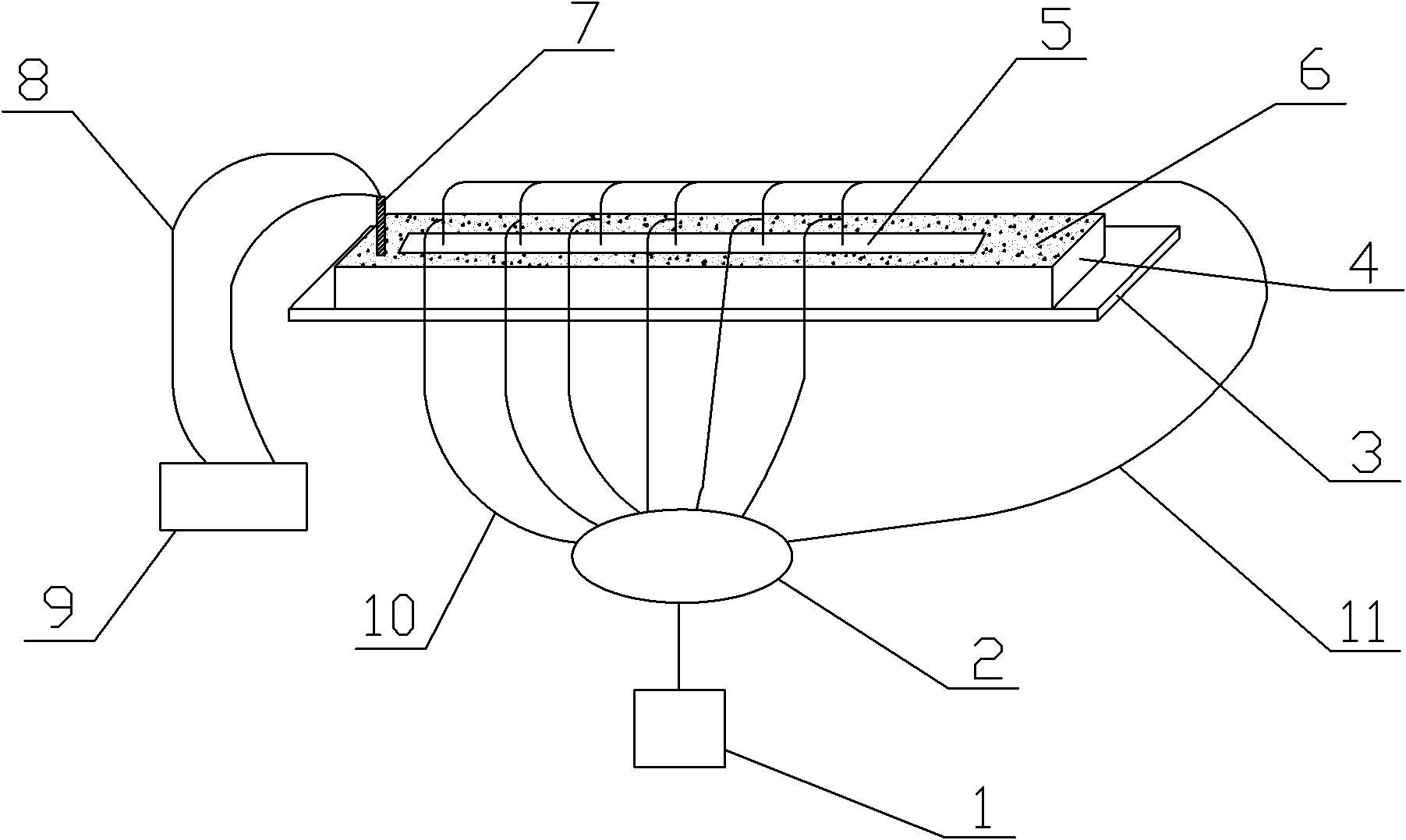
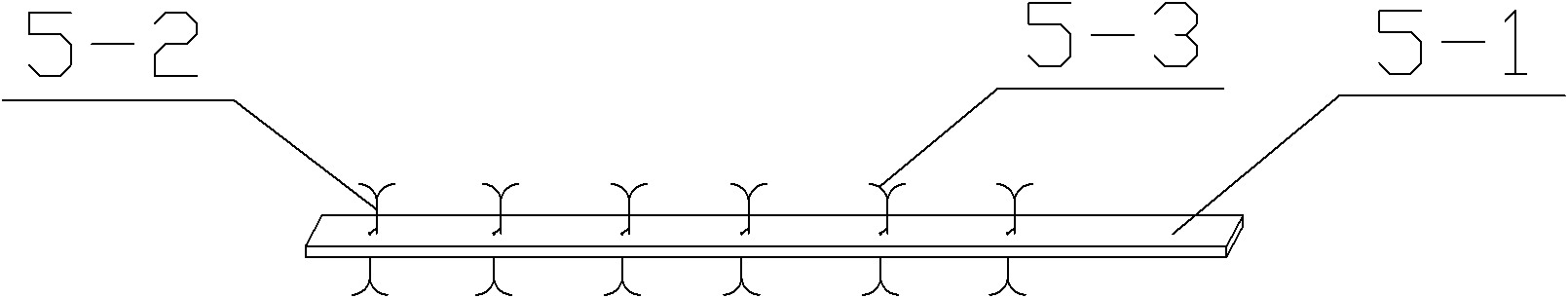
[0023] Such as figure 1 and figure 2 Shown a kind of explosive detonation velocity measuring device, comprises detonation velocity instrument 1, and the signal formation circuit 2 that is connected with detonation velocity instrument 1, also comprises backing plate 3, is installed on the backing plate 3 and is used to place the medicine frame 4 of explosive 6, place The continuous probe 5 on the surface of the explosive 6 and the detonator 7 placed in the charge frame 4, and the detonator 9 connected to the detonator 7 through the detonating wire 8; the continuous probe 5 is formed by a fixed plate 5-1, uniformly It consists of a plurality of supports 5-2 fixed on the fixed plate 5-1 arranged in a straight line, and a sensing element 5-3 wound on the supports 5-2. The fixed frame 5-1 is located on each support A through hole is opened on one side of the object 5-2, and the sensing element 5-3 passes through the through hole and is divided into upper and lower parts by the fi...

Embodiment 2

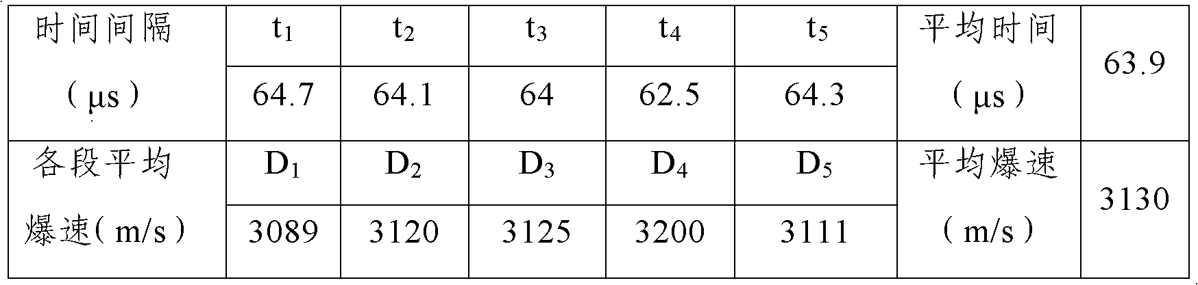
[0026] A method for measuring the detonation velocity of explosives: placing explosives 6 in the charge frame 4 of the explosive detonation velocity measuring device, detonating the explosives 6 through the detonator 9 and the detonator 7, when the detonation wave reaches the first one on the continuous probe 5 In the case of the sensing element 5-3, the sensing element 5-3 perceives the information of the detonation wave arrival under the effects of high temperature and (or) high pressure, ionization, and luminescence accompanied by the detonation wave front, and passes the signal Form a circuit and convert it into an electrical signal, measure the time interval t between the two signals given by the first sensing element and the second sensing element on the continuous probe 5 with the detonation velocity meter 1, and then according to the two The average detonation velocity D in the explosive section can be obtained by the distance of the sensing element. As the detonation p...


PUM


Abstract

The invention discloses a device for measuring the detonating velocity of explosive. The device comprises a detonating velocity meter, a signal forming circuit connected with the detonating velocity meter, a base plate, an explosive frame arranged on the base plate and used for placing the explosive, a continuous probe arranged on the surface of the explosive, a detonator arranged in the explosive frame, and an exploder connected with the detonator through an explosion initiation line; and the continuous probe consists of a fixed plate, a plurality of supporting objects which are uniformly fixed on the fixed plate in a line, and sensing elements winding on the supporting objects. The invention also discloses a method for measuring the detonating velocity by using the device for measuring the detonating velocity of the explosive. The method for measuring the detonating velocity is simple and practical, and a plurality of groups of data and continuous detonating velocities in the whole explosive detonation are measured, so that the change condition of the detonating velocity is reflected.

Description

technical field [0001] The invention belongs to the technical field of explosive detonation velocity measurement, and in particular relates to an explosive detonation velocity measurement device and a measurement method. Background technique [0002] Explosive compounding is a new type of processing technology produced in the field of explosive processing. It is mainly used to realize large-area welding of stainless steel, non-ferrous metals, rare metals and low alloy steel, stainless steel, carbon steel or other materials to obtain layered metal composite materials. . The clad metal of this kind of composite material has excellent properties such as corrosion resistance, high temperature resistance and wear resistance, while the base metal has good mechanical properties and processing properties. In this way, a large amount of stainless steel, non-ferrous metals, and rare metals can be saved. With the continuous development of industry, this composite material has been wi...

Claims


Application Information

Patent Timeline
Patent Type & Authority Applications(China)
IPC IPC(8): G01P3/00
Inventor 杨学山汪洋高文柱朱磊吴江涛惠洪涛张鹏辉黄杏利王媛郭悦霞李进军赵惠
Owner XIAN TIANLI CLAD METAL MATERIALS
Why Eureka
Try Eureka