Intelligent antenna equipment and method for supporting independent intersystem electric regulation

A smart antenna and heterogeneous system technology, applied to antennas, antenna arrays, circuits, etc., can solve problems such as adjusting inclination angles, optimization, and many sky resources, and achieve the effects of improving performance and reducing occupancy

Active Publication Date: 2011-06-01
CHINA MOBILE COMM GRP CO LTD
View PDF5 Cites 36 Cited by
  • Summary
  • Abstract
  • Description
  • Claims
  • Application Information

AI Technical Summary

Problems solved by technology

[0005] 1. Existing dual-polarization smart antenna equipment generally adopts the structure of ±45-degree radiation unit arrangement. The technology is mature and stable in the AB frequency band, but it cannot cover the C frequency band, so it cannot support TD-SCDMA system and TD-LTE System Common Antenna Feed Use
[0006] 2. Two antennas need to be designed to support the LTE system and the 3G system respectively, and the two antennas carry two RRUs (Radio Remote Unit, radio frequency remote module) respectively, thus occupying more antenna resources
[0007] 3. Based on different frequency bands, the inclination angle cannot be completely independently optimized and adjusted according to the coverage difference caused by the frequency band. It is relatively difficult to realize electric adjustment in the entire wide frequency band, and it will reduce the performance of antenna equipment to a certain extent.
[0008] To sum up, the existing smart antenna equipment cannot support different systems (such as TD-SCDMA system and TD-LTE system) to use common antenna feeds, occupying a lot of antenna resources, and the performance of antenna equipment is low

Method used


Image

  • Intelligent antenna equipment and method for supporting independent intersystem electric regulation
  • Intelligent antenna equipment and method for supporting independent intersystem electric regulation
  • Intelligent antenna equipment and method for supporting independent intersystem electric regulation

Examples


Embodiment Construction

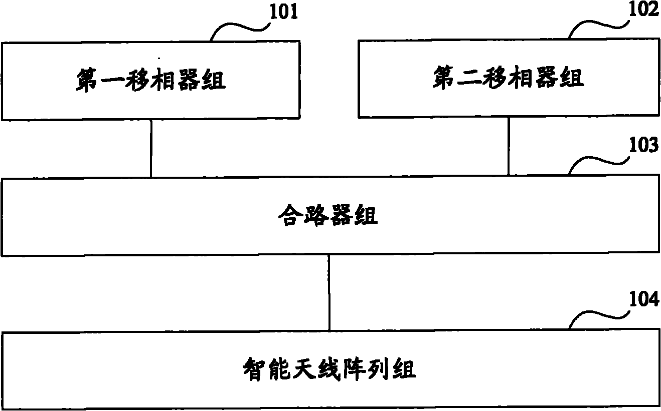
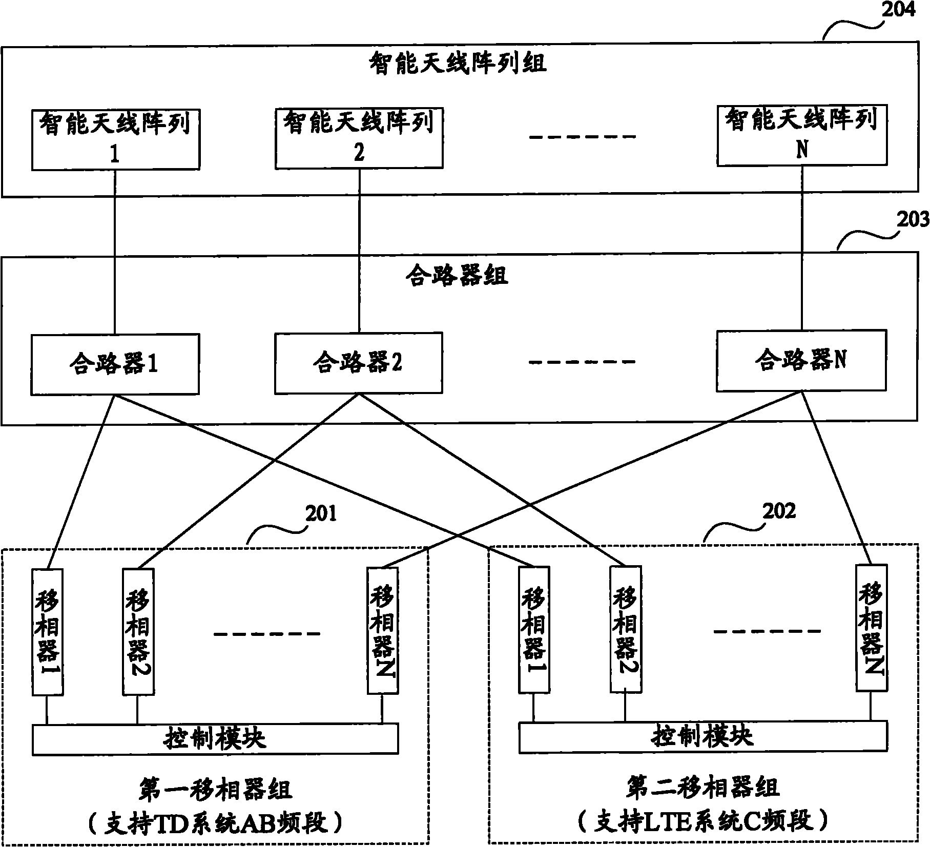
[0038] In order to provide a solution for realizing the common antenna feeder of different systems, reducing the occupation of antenna resources and improving the performance of antenna equipment, the embodiment of the present invention provides a smart antenna equipment and method that supports independent electrical regulation of different systems, and the following is attached with the description The drawings illustrate the preferred embodiments of the present invention, and it should be understood that the preferred embodiments described here are only used to illustrate and explain the present invention, and are not intended to limit the present invention. And in the case of no conflict, the embodiments in the present application and the features in the embodiments can be combined with each other.

[0039] The smart antenna is composed of multiple antenna array groups. Each antenna array group has an approximate pattern and is arranged according to certain rules. In the em...


PUM


Abstract

The invention discloses intelligent antenna equipment and method for supporting independent intersystem electric regulation. The intelligent antenna equipment comprises a first phase shifter group, a second phase shifter group, a combiner group and an intelligent antenna array group, wherein each phase shifter of the first phase shifter group is used for receiving a first signal which is transmitted from or to a first system, and regulating the phase shift amount of the first signal according to requirements of a first working frequency range of the working of the first system on a downward dip angle; each phase shifter of the second phase shifter group is used for regulating the phase shift amount of a second signal from a second system; each combiner in the combiner group is used for receiving two paths of regulated signals and combining the signals to be sent to an intelligent antenna array; signals transmitted by the intelligent antenna array are partitioned into two paths of signals which are then respectively provided for the first phase shifters and the second phase shifters; and each intelligent antenna array in the intelligent antenna array group is used for sending and receiving the signals. By adopting the technical scheme, the utilization of inter-system sharing an antenna feeder is realized, the occupation of roof surface resources is reduced, and the antenna equipment performance is improved.

Description

technical field [0001] The invention relates to the technical field of mobile communication, in particular to a smart antenna device and method supporting independent electrical adjustment of different systems. Background technique [0002] With the development of mobile communication technology, in addition to the 3G network under construction such as TD-SCDMA (Time Division-Synchronous Code Division Multiple Access, Time Division Synchronous Code Division Multiple Access), there will also be TD-LTE (Time Division-Synchronous Code Division Multiple Access). Long Term Evolution, long-term evolution of time-division synchronization) 4G network. In this case, there will inevitably be a network development situation where multiple standards coexist. At present, various technical standards have independent antenna feeder systems, and the frequency bands used are also very different. However, due to the existence of multi-standard networks of multiple operators, and considering...

Claims


Application Information

Patent Timeline
Patent Type & Authority Applications(China)
IPC IPC(8): H01Q3/30H01Q21/00
Inventor 马欣
Owner CHINA MOBILE COMM GRP CO LTD
Why Eureka
Try Eureka