Elevator power saving system and power saving method
A technology for elevators and elevator cars, applied in the directions of elevator energy efficiency, sustainable building, climate sustainability, etc., can solve the problems of long standby time and low elevator operation rate, and achieve the effect of energy saving
- Summary
- Abstract
- Description
- Claims
- Application Information
AI Technical Summary
Problems solved by technology
Method used
Image

Examples
no. 1 example
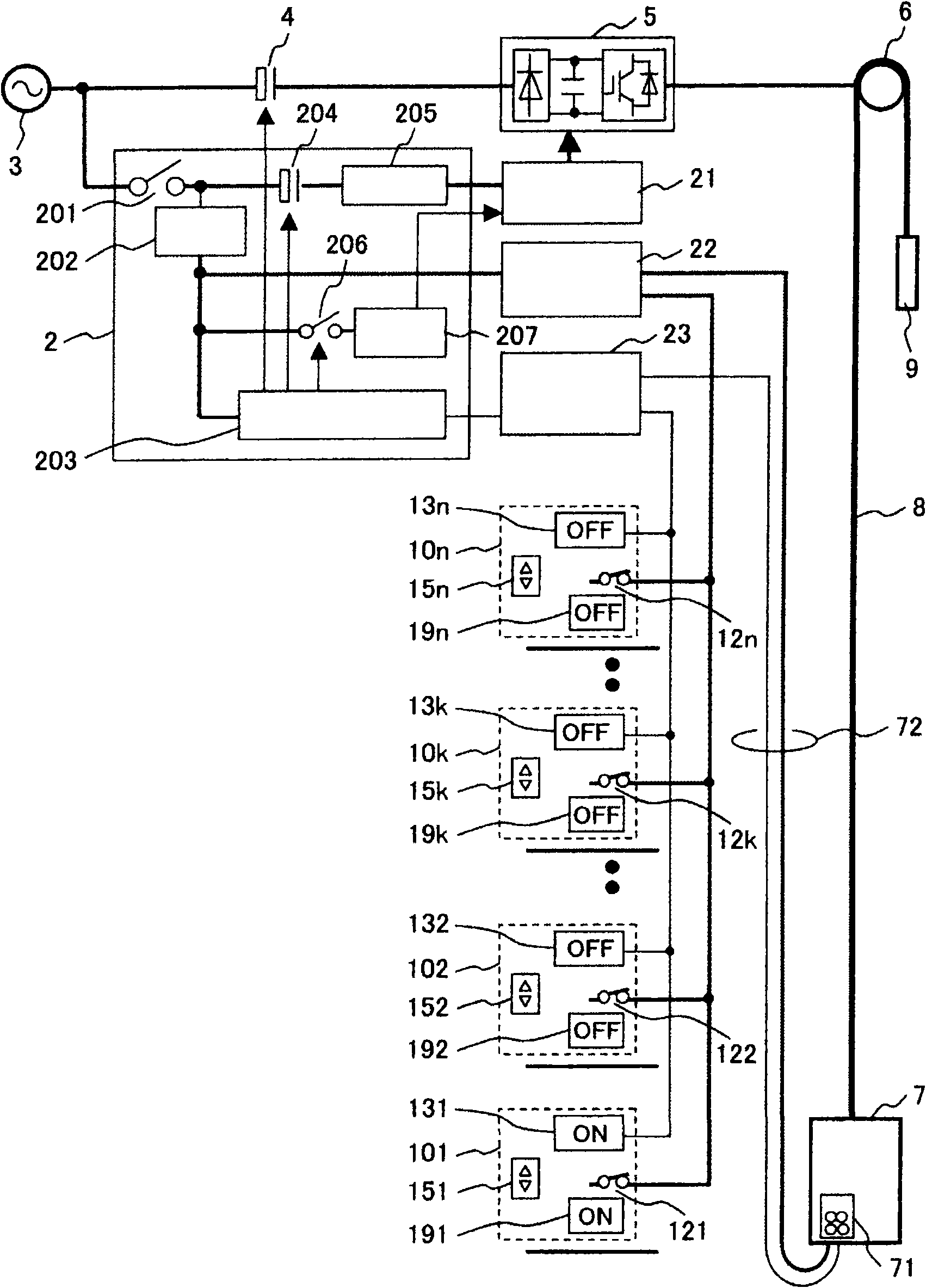
[0060] figure 1 It is a configuration diagram of the power saving system of an elevator according to the first embodiment of the present invention.
[0061] Power is supplied to the motor and the hoist 6 from the power supply 3 through the switch 4 and the power converter 5 . Elevator car 7 and counterweight 9 are suspended by slings 8 and driven by hoist 6 . Such as figure 1As shown, the power converter 5 is composed of a rectifier circuit, a smoothing capacitor, and an inverse conversion circuit (inverter). The power converter 5 is driven and controlled by a drive control section 21 . The actual power converter 5 includes components such as a current sensor not shown, a discharge circuit for suppressing DC overvoltage during regenerative operation, and a noise filter, in addition to the components described above.
[0062] The overall control of the elevator system is performed by the elevator control device 2, which responds to the registration of the elevator hall call...
no. 2 example
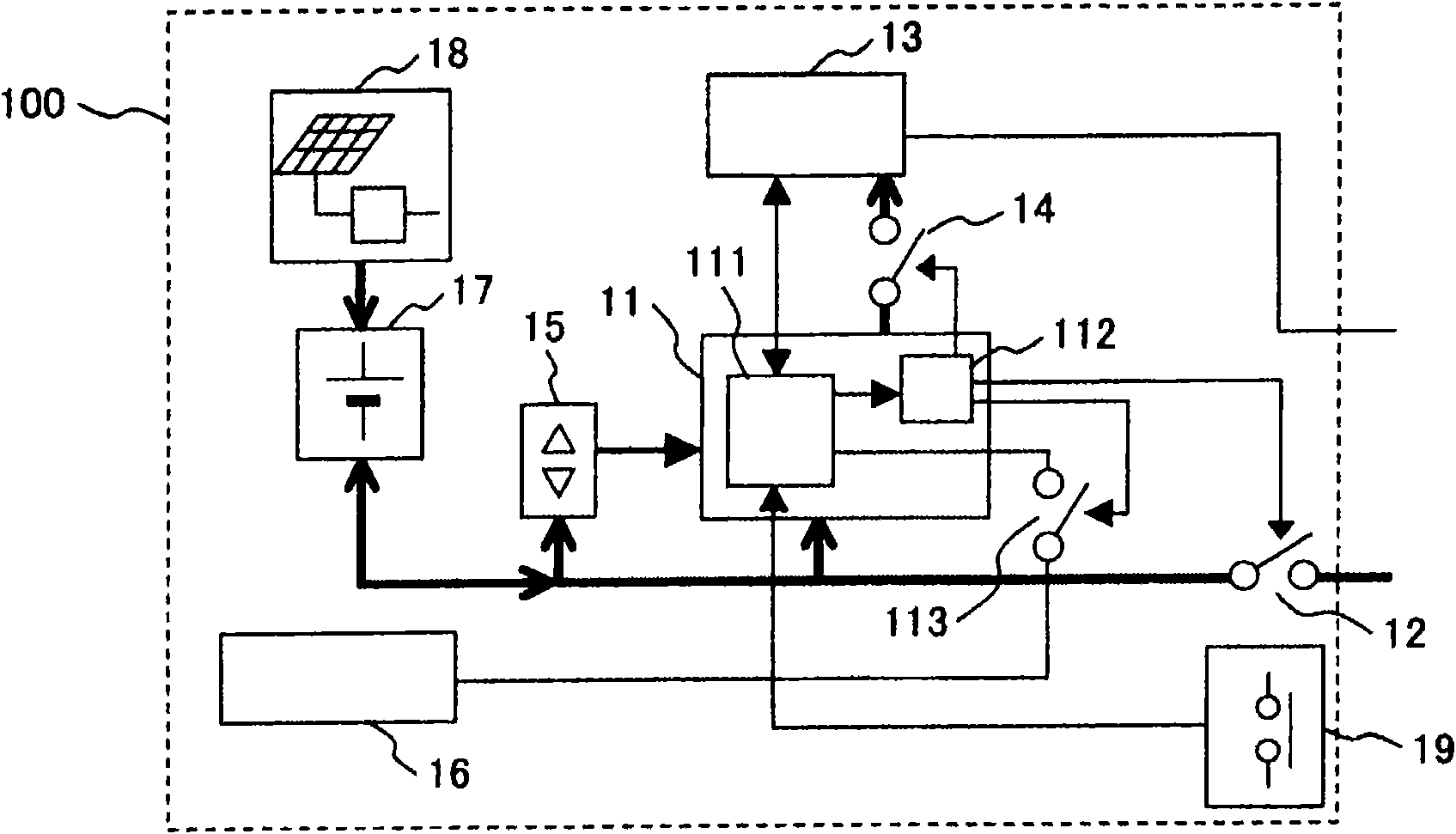
[0091] Refer to the following Figure 5 with Image 6 A second embodiment of the present invention will be described.
[0092] Figure 5 It is a configuration diagram of an elevator power saving system according to a second embodiment of the present invention. exist Figure 5 In the overall structure of the elevator and figure 1 The same parts are represented by the same symbols, and only the different parts are described. In this embodiment, a method in which communication and power supply overlap (for example, using power lines for transmission) is adopted. Thus, in Figure 5 will be in figure 1 The elevator lobby and the elevator car power supply part (main power supply for control) 22 and the communication control part 23 separately provided in the elevator hall are combined into a power supply communication part 24. The wiring of the elevator hall call devices 101-10n leading to each floor from the power supply communication part 24 is figure 1 respectively, and ...
no. 3 example
[0096] Refer to the following Figure 7 with Figure 8 A third embodiment of the present invention will be described. exist Figure 7 with Figure 8 In , the same parts are denoted by the same symbols, and their descriptions are omitted.
[0097] Figure 7 It is a configuration diagram of an elevator power saving system according to a third embodiment of the present invention. Figure 8 is a block diagram of an elevator hall call device in the third embodiment of the present invention. Figure 7 with Figure 8 and figure 1 with figure 2 The difference is that in Figure 7 with Figure 8 Among them, the communication with the communication control unit 23, the elevator hall communication devices 131-13n, and the elevator car 7 is performed wirelessly.
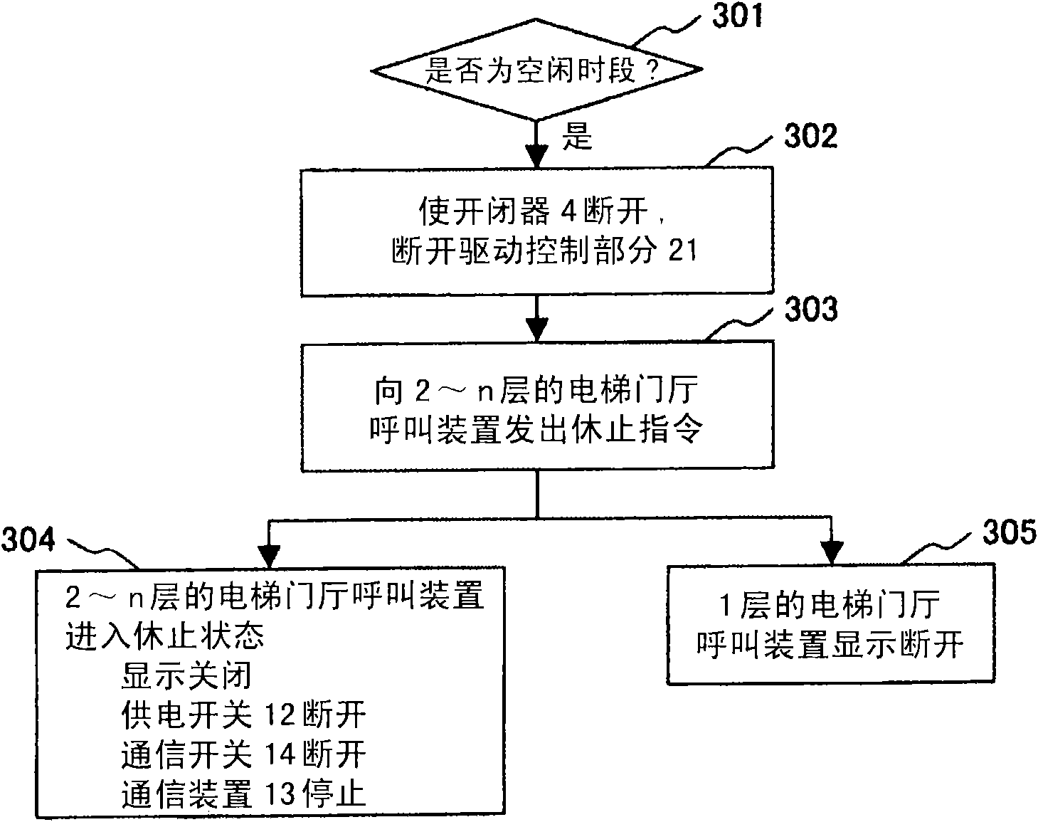
[0098] In the third embodiment, the flow when entering the suspend state and the flow when resuming from the suspend state are the same as image 3 with Figure 4 are the same, so the description of these processes...
PUM
 Abstract
Description
Claims
Application Information
 - R&D Engineer
- R&D Manager
- IP Professional
- Industry Leading Data Capabilities
- Powerful AI technology
- Patent DNA Extraction
Browse by: Latest US Patents, China's latest patents, Technical Efficacy Thesaurus, Application Domain, Technology Topic.
© 2024 PatSnap. All rights reserved.Legal|Privacy policy|Modern Slavery Act Transparency Statement|Sitemap