Hydraulic working rig

A working machine and hydraulic technology, which is applied in the direction of mechanical equipment, engine components, engine control, etc., can solve the problems of unable to regenerate the filter, the temperature rise of the exhaust gas, etc., and achieve the effect of improving reliability and stabilizing purification treatment

Active Publication Date: 2011-06-08
NIHON KENKI CO LTD
View PDF7 Cites 15 Cited by
  • Summary
  • Abstract
  • Description
  • Claims
  • Application Information

AI Technical Summary

Problems solved by technology

Therefore, in a small hydraulic excavator with simplified equipment and no discharge control of the hydraulic pump, etc., it is difficult to raise the temperature of the exhaust gas to the temperature required for regenerating the filter, and it is impossible to reduce the accumulation in the filter. Problems with burning particulate matter in the filter to regenerate the filter

Method used


Image

  • Hydraulic working rig
  • Hydraulic working rig
  • Hydraulic working rig

Examples


Embodiment Construction

[0071] Hereinafter, a small hydraulic excavator will be taken as an example as a hydraulic working machine having an exhaust gas purification device according to an embodiment of the present invention, and will be described in detail based on the drawings.

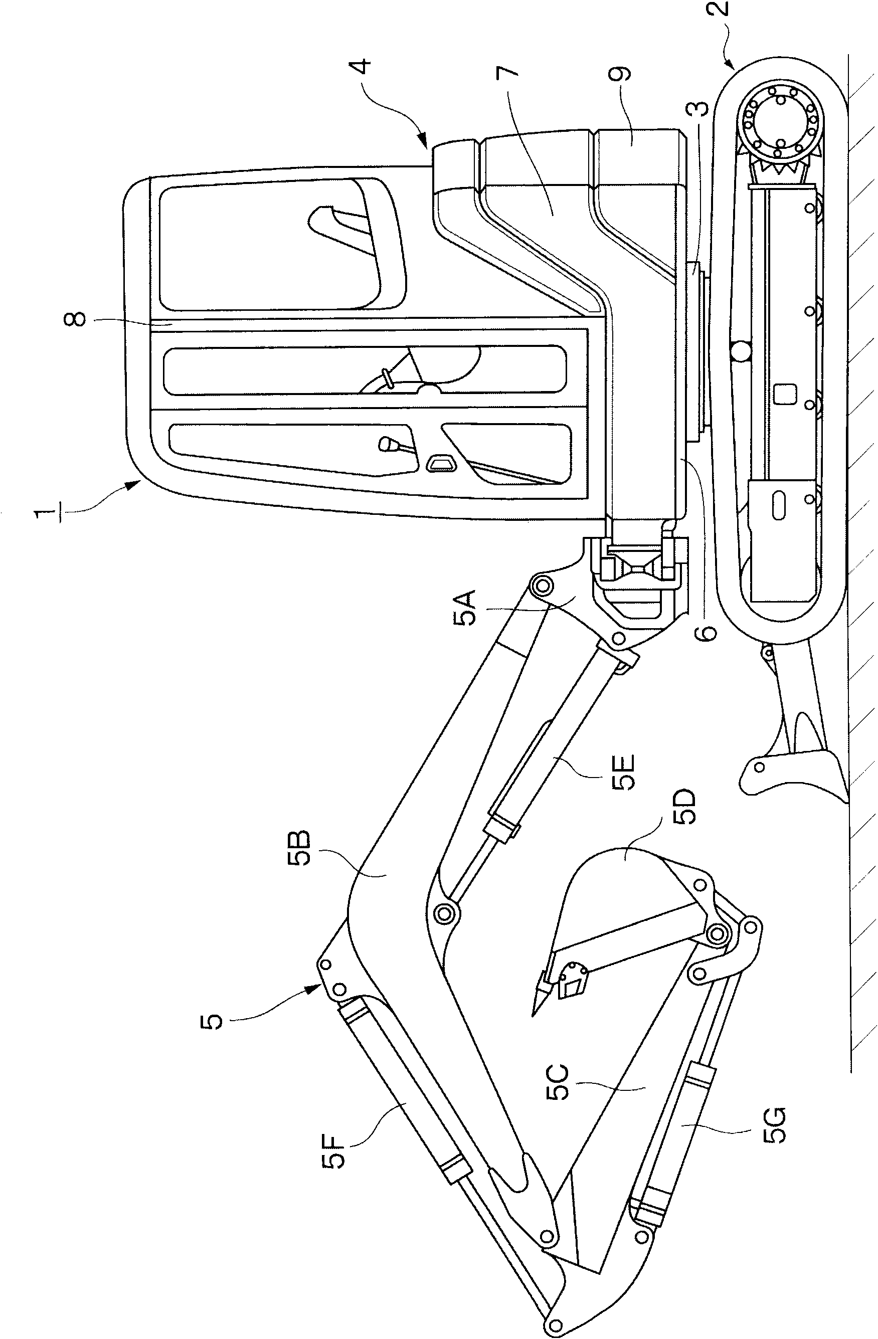
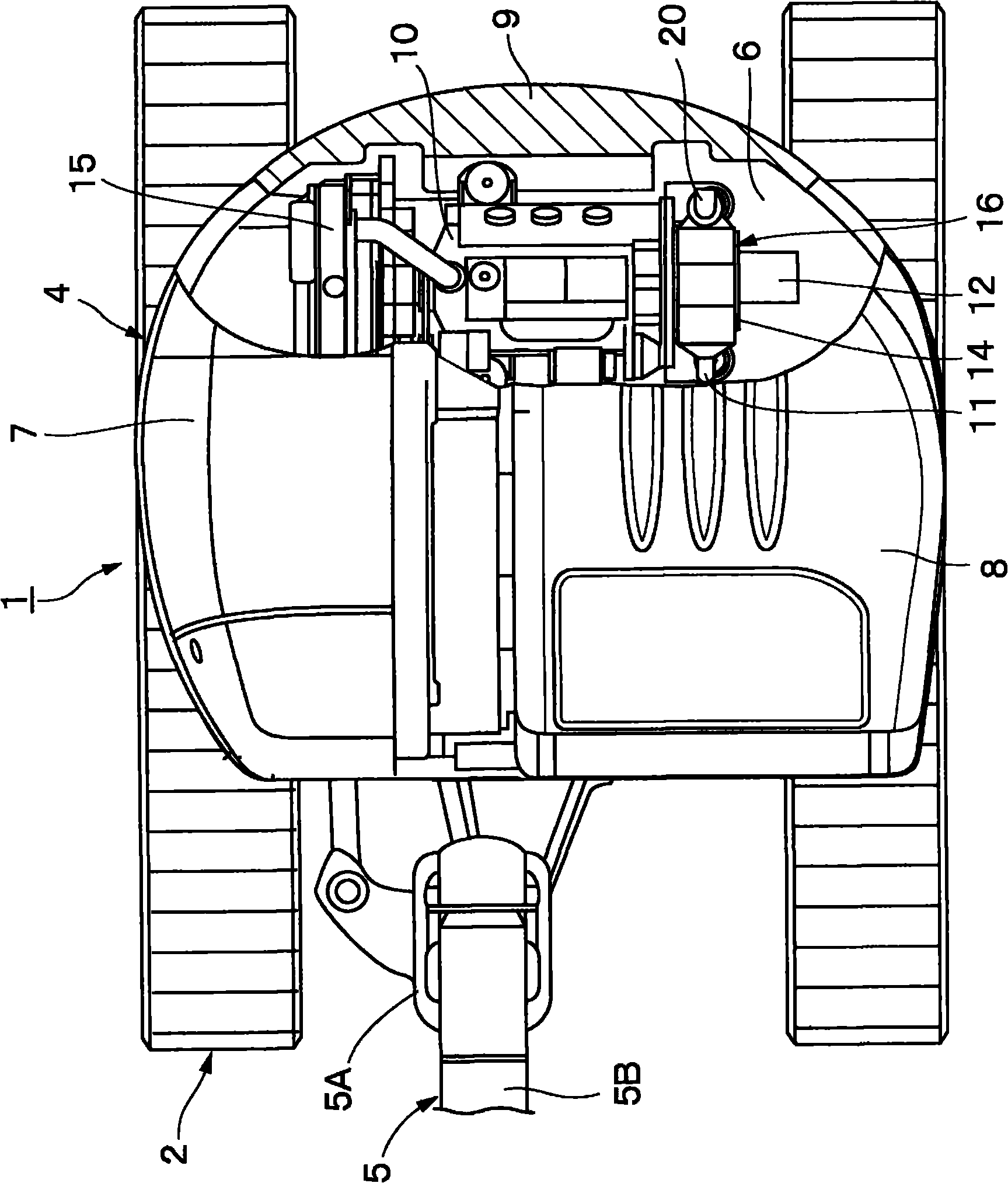
[0072] here, Figure 1 to Figure 7 The first embodiment of the present invention is shown. In the figure, reference numeral 1 denotes a small hydraulic excavator used for excavation work of sandy soil and the like. This hydraulic excavator 1 generally includes: a crawler-type lower traveling body 2 capable of self-propelling; 4; and the working device 5 provided on the front side of the upper slewing body 4 so as to be capable of pitching.

[0073] Here, the working device 5 is configured as a swing post type working device, and the working device 5 includes, for example, a swing post 5A, a boom 5B, an arm 5C, a bucket 5D as a working tool, and a swing cylinder. (swing cylinder) (not shown), boom cylinder (boom cylinder...


PUM


Abstract

The invention provides a hydraulic working rig, which is equipped with a waste gas purifier and can generate hydraulic load in a hydraulic loop to increase the temperature of the waste gas of an engine. In the hydraulic working rig, a load input valve (36) used to heat the waste gas is arranged on a path where the pressure oil from a hydraulic pump (12) is supplied to an output pipe (26) of a hydraulic cylinder (29). When the hydraulic cylinder (29) stops, the temperature of the waste gas flowing into a purifier (19) for removing particles is lowered. When regeneration treatment of the purifier (19) is required, the load input valve (36) is shifted from a neutral position (d) to shift positions (e) and (f). Therefore, any one of first and second safety valves (37, 38) generating hydraulic load may increase the load of the engine (10) of the hydraulic pump (12), thereby increasing fuel consumption and raising the temperature of waste gas.

Description

technical field [0001] The present invention relates to a hydraulic working machine having an exhaust gas purification device suitable for removing harmful substances from exhaust gas such as a diesel engine. Background technique [0002] Generally speaking, a construction machine such as a hydraulic excavator consists of a self-propelled undercarriage, an upper revolving body rotatably mounted on the undercarriage, and a pitch-movable upper revolving body installed in front of the upper revolving body. Side working device configuration. In the upper revolving body, an engine for driving a hydraulic pump is installed at the rear of the revolving frame, and a driver's cab, a fuel tank, a working oil tank, and the like are installed on the front side of the revolving frame. [0003] Here, a diesel engine is generally used as an engine serving as a prime mover of a hydraulic excavator or the like. In addition, the exhaust gas discharged from the diesel engine usually contains...

Claims


Application Information

Patent Timeline
Patent Type & Authority Applications(China)
IPC IPC(8): F01N3/023F02D29/04F15B15/18
CPCY02T10/40E02F9/0866E02F9/2221E02F9/2246F01N3/021F01N3/023F01N11/002F01N2260/04F01N2590/08F01N2900/1606F02D41/029F02D41/1446
Inventor 吉田肇石井元野口修平藤井笃人
Owner NIHON KENKI CO LTD
Why Eureka
Try Eureka