Blood vessel characteristics measurement device and method for measuring blood vessel characteristics

A measuring device and technology of measuring position, which are applied in the directions of blood flow measurement, diagnostic recording/measurement, catheter, etc., can solve the problems such as the decrease of measurement accuracy, and achieve the effect of lightening the burden and high measurement accuracy

Inactive Publication Date: 2011-06-08
UNIV OF TSUKUBA
View PDF3 Cites 10 Cited by
  • Summary
  • Abstract
  • Description
  • Claims
  • Application Information

AI Technical Summary

Problems solved by technology

[0007] The present invention takes the above problems into consideration, and solves the

Method used


Image

  • Blood vessel characteristics measurement device and method for measuring blood vessel characteristics
  • Blood vessel characteristics measurement device and method for measuring blood vessel characteristics
  • Blood vessel characteristics measurement device and method for measuring blood vessel characteristics

Examples


Embodiment 1

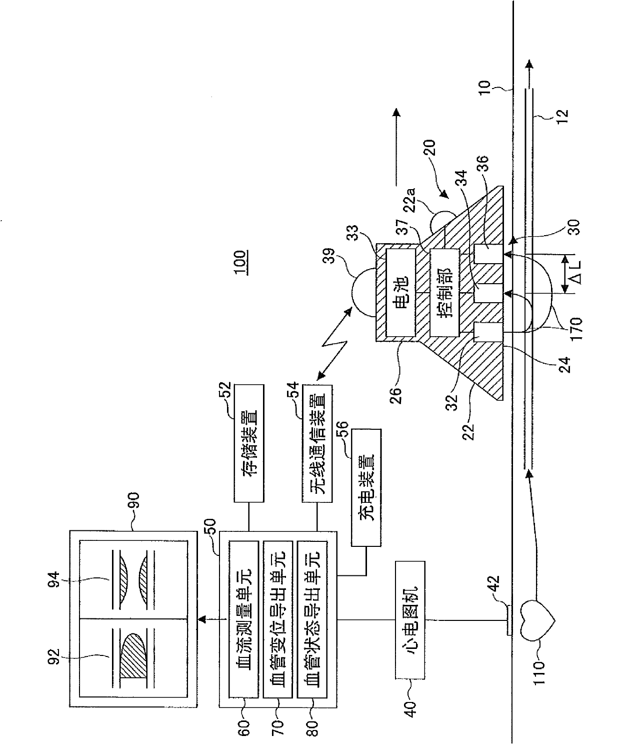
[0044] figure 1 It is a system diagram showing a schematic configuration of Embodiment 1 of the blood vessel characteristic measuring device of the present invention. Such as figure 1 As shown, the blood vessel characteristic measurement device 100 includes a mobile blood flow measurement unit 20 , an optical sensor unit 30 , an electrocardiograph (electrocardiogram measurement unit) 40 , and a control device 50 . The blood flow measurement unit 20 is used to measure the blood flow of the subject at a position facing the skin surface 10 of the measurement area. The sensor unit 30 has an optical sensor built in the blood flow measurement unit 20 to measure the blood flow flowing in the blood vessel in a non-contact manner. The electrocardiograph (electrocardiogram measuring unit) 40 is used to measure the cardiac potential and output the cardiac potential signal. The control device 50 obtains the displacement of the inner wall of the blood vessel and the displacement of the ...

Embodiment 2

[0104] Figure 8 It is a system configuration diagram showing a cerebrovascular property measuring system of Example 2 using the blood vessel property measuring device of the present invention. Such as Figure 8 As shown, the cerebrovascular characteristic measurement system 200 has a blood vessel characteristic measurement device 210 and a data management device 250 . The data management device 250 is used to manage the data measured by the blood vessel characteristic measurement device 210 . It should be noted that although the Figure 8 Although the blood vessel characteristic measuring device 210 is shown only on one side of the head in the figure, the same configuration is also shown on the opposite side (the back side of the paper).

[0105] The blood vessel characteristic measurement device 210 has a blood flow measurement unit 220 , a control unit 230 , and a wireless communication device 240 . The blood flow measurement unit 220 is composed of a mesh base 222 form...


PUM

PropertyMeasurementUnit
Diameteraaaaaaaaaa

Abstract

A blood vessel characteristics measurement device is provided with a blood flow measurement unit held at a position opposite to a skin surface in a measured region of an examinee, an optical sensor unit built in the blood flow measurement unit, an electrocardiographic monitor, and a control device. The control device has a blood flow measuring means, a blood vessel displacement deriving means, and a blood vessel condition deriving means . The blood flow measuring means measures the displacement of a blood vessel and blood vessel surrounding tissue due to a blood flow in accordance with the intensity of light when light receiving units receive the light projected from a light emitting unit of a sensor unit. The blood vessel displacement deriving means derives the displacement of an inner wall of a blood vessel in accordance with a blood vessel and blood vessel surrounding tissue. The blood vessel condition deriving means seeks a pulse transmission speed in each measurement position in accordance with a phase difference between an electrocardiographic signal waveform of the electrocardiographic monitor and a detection signal waveform obtained from the receiving units, thereby deriving the displacement condition of the inner wall of the blood vessel from the pulse transmission speed.

Description

technical field [0001] The present invention relates to a blood vessel property measuring device and a blood vessel property measuring method for measuring the state in a blood vessel flowing with blood in a non-contact manner. Background technique [0002] For example, when the blood discharged from the heart flows in the blood vessel due to the pressure, the inner diameter of the blood vessel expands due to the pressure in the part where the high pressure area is conducted. A pulse wave velocity measuring device that measures changes inside a blood vessel (artery) by measuring the conduction velocity (also known as pulse wave velocity) transmitted by the enlarged diameter portion of the blood vessel is currently being developed (for example, Patent Document 1: Japanese Patent Laid-Open No. 8 -257002 Bulletin). [0003] As far as the pulse wave conduction velocity measurement device is concerned, if it is calculated from the predetermined position of each cycle of the lead...

Claims


Application Information

Patent Timeline
IPC IPC(8): A61B5/02A61B10/00
CPCA61B5/6814A61B5/0285A61B5/02125A61B5/417A61B5/0295A61B2562/046A61B2562/0233A61B5/0261A61B5/02007A61B5/02A61B5/026A61B5/14
Inventor 山海嘉之
Owner UNIV OF TSUKUBA
Why Eureka
Try Eureka