Driving means and device for working sheet-like material

A driving device and equipment technology, applied in the direction of hoisting devices, portable lifting devices, manufacturing tools, etc., can solve the problem of reducing the maximum tensile strength of the belt, reducing the width of the components, reducing the possibility of collision, and reducing the tension Effect

Active Publication Date: 2011-06-08
NIVORA IP
View PDF7 Cites 2 Cited by
  • Summary
  • Abstract
  • Description
  • Claims
  • Application Information

AI Technical Summary

Problems solved by technology

When the diameter of the rollers is reduced, the belt has a smaller bend radius, which reduces the maximum tensile strength of the belt

Method used


Image

  • Driving means and device for working sheet-like material
  • Driving means and device for working sheet-like material
  • Driving means and device for working sheet-like material

Examples


Embodiment Construction

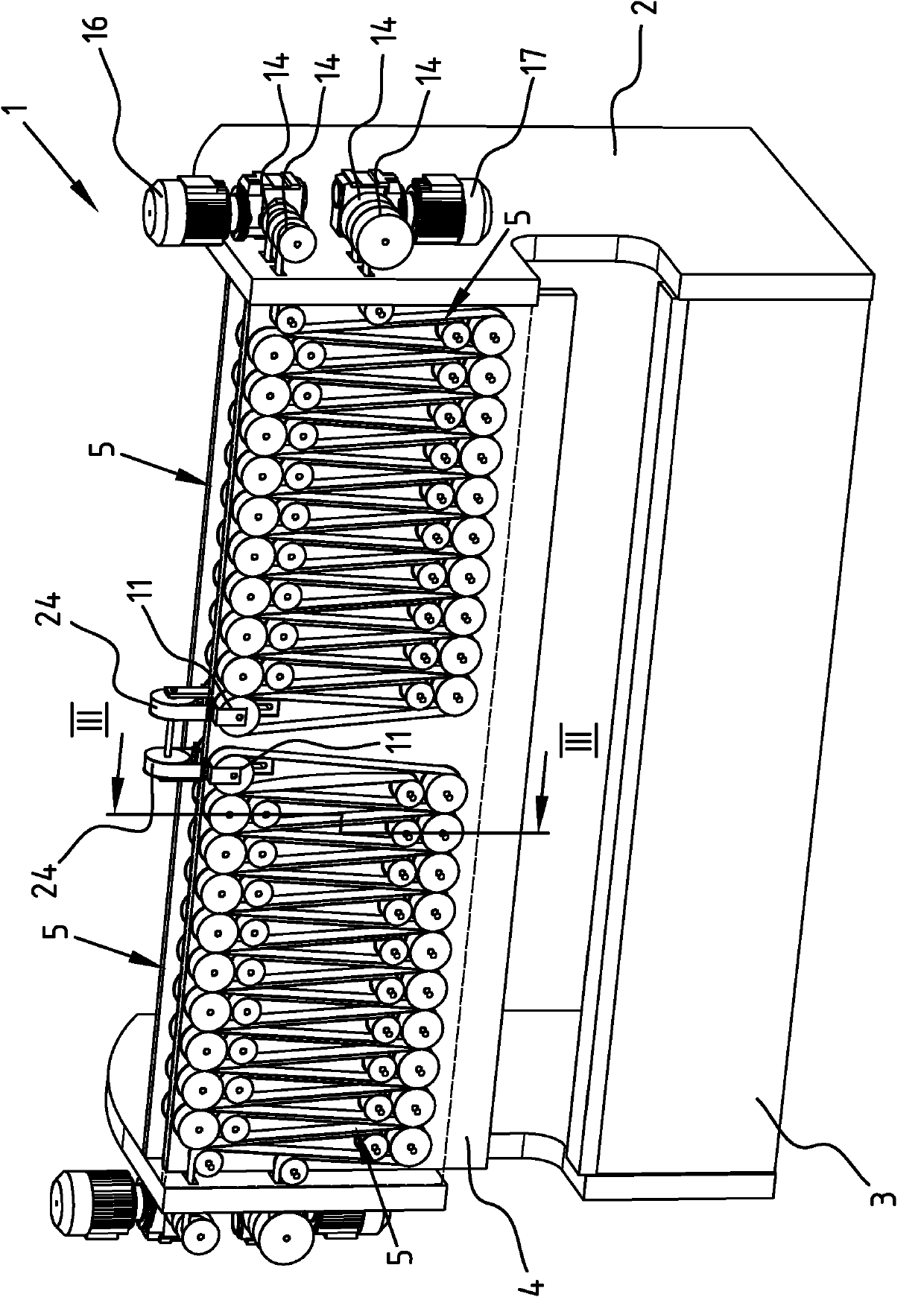
[0035] exist figure 1 , a perspective view of an embodiment of a device 1 according to the invention is shown. The apparatus 1 has a so-called C-frame 2 with: a lower beam 3 fixed to the C-frame 2; and an upper beam 4 which is movable.

[0036] Four drive devices 5 are arranged adjacent to the upper beam 4 . Two drives 5 are arranged on the front side of the beam 4 , while two other drives 5 are arranged on the rear.

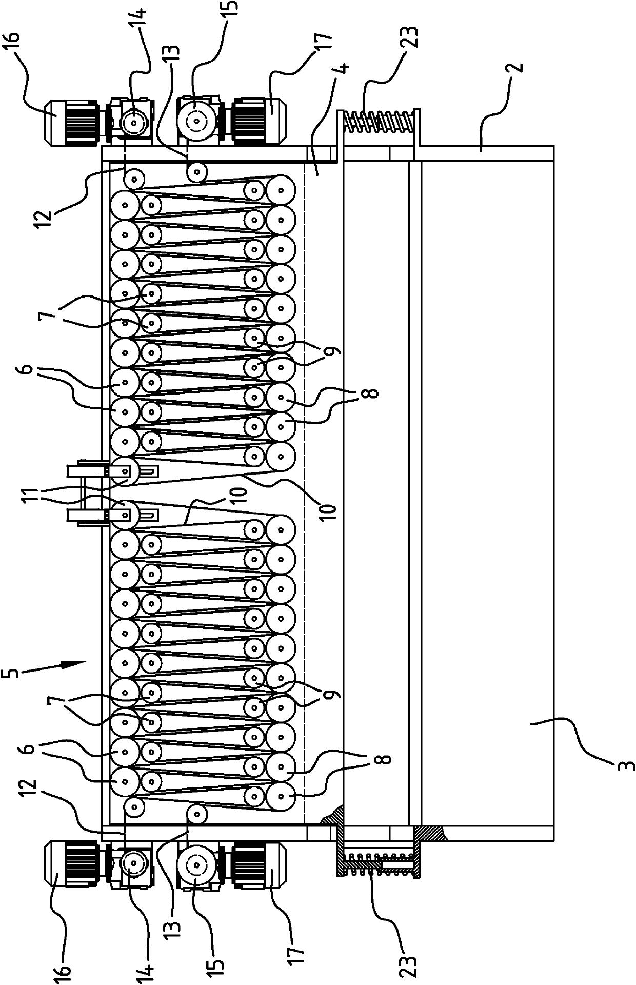
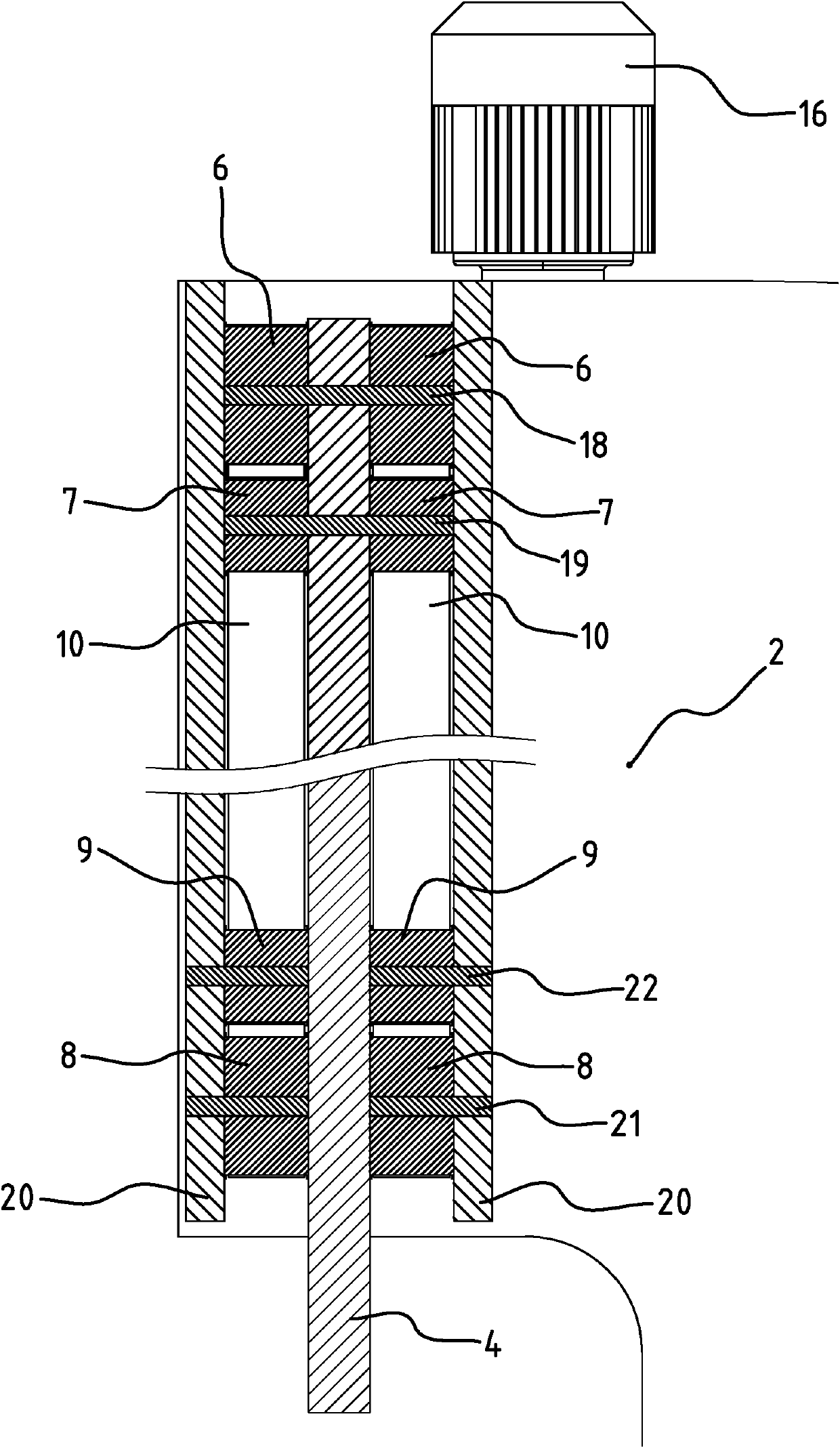
[0037] Each drive 5 has a first set of a row of main rollers 6 and a row of auxiliary rollers 7 and a second set of a row of main rollers 9 and a row of auxiliary rollers 8 .

[0038] Each drive 5 has a belt 10 which winds along the length of the beam 4 between the first set of main rollers 6 and the second set of main rollers 9 and between the first set of auxiliary rollers 7 and the second set The auxiliary roller 8 detours back and forth. Each drive 5 has an idler pulley 11 at which the belt 10 changes direction.

[0039] The belt 10 has a first end 12 a...


PUM


Abstract

The invention relates to driving means for displacing two elongate members, the driving means comprising: a first set of at least a row of primary rollers (6) and a row of secondary rollers (7); a second set of at least a row of primary rollers (9) and a row of secondary rollers (8); wherein the first set is connected to a first member and the second set is connected to a second member; and wherein a belt (10) serpentines between the primary rollers (6) of the first set and the primary rollers (9) of the second set along the length of the members and serpentines back between the secondary rollers of the first set and the secondary rollers of the second set.

Description

technical field [0001] The invention relates to a drive that can be used in a plant for processing sheet-like material, such as a press brake for bending steel sheets. Background technique [0002] European Patent Application No. 0 384 529 discloses a drive for a press brake. A disadvantage of this type of drive is that there is a certain limit to the available pressure per unit length of the beam. This limitation is for example a result of the tensile strength of the belt. The increase in belt width required to increase tensile strength will limit the maximum bending angle of the device for a particular product when bending sheet material. By increasing the width of the belt, the width of the beam increases, which in turn leads to an increased probability of collisions between the sheet material and the beam. [0003] Another limitation has to do with the motor used to drive the belt. If the stress on the device increases, the power of the motor will also increase, resu...

Claims


Application Information

Patent Timeline
Patent Type & Authority Applications(China)
IPC IPC(8): B30B1/30B21D5/02B66D3/06
CPCB30B9/3071B30B1/30B21D5/02
Inventor R·布伦廷克
Owner NIVORA IP
Why Eureka
Try Eureka