Gas detection device

A technology of gas detection and equipment, applied in the detection of the presence and/or concentration of gas, and the field of vehicles, which can solve the problems of complex and expensive equipment

Inactive Publication Date: 2011-06-08
KONINKLIJKE PHILIPS ELECTRONICS NV
View PDF2 Cites 12 Cited by
  • Summary
  • Abstract
  • Description
  • Claims
  • Application Information

AI Technical Summary

Problems solved by technology

[0004] The device is complex and expensive

Method used


Image

  • Gas detection device
  • Gas detection device
  • Gas detection device

Examples


Embodiment Construction

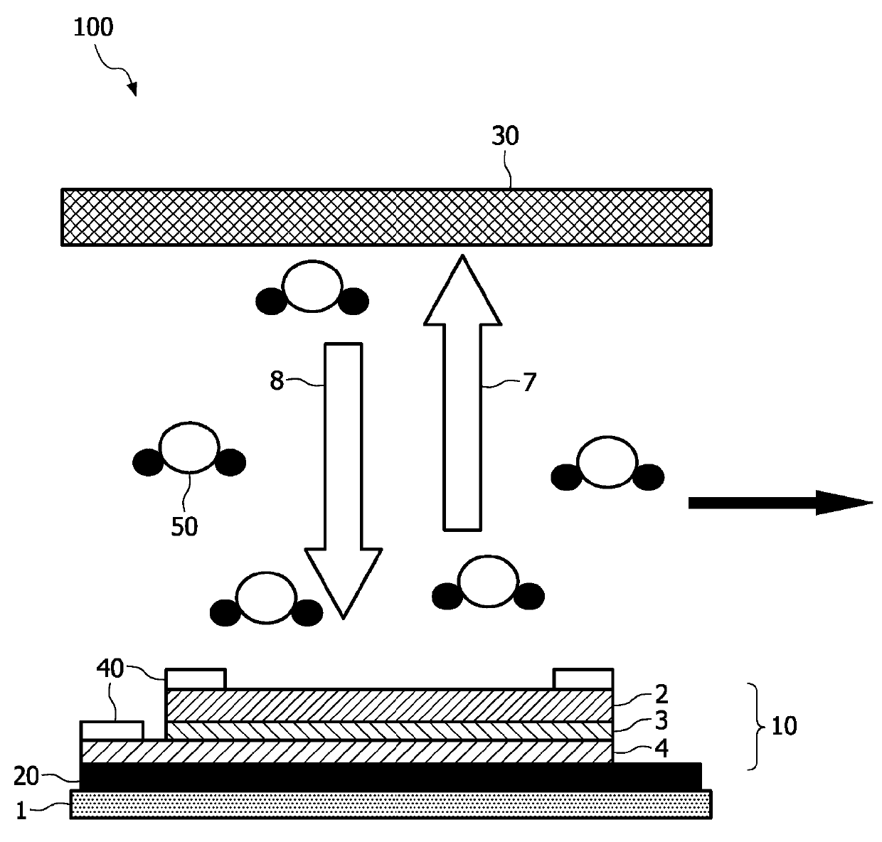
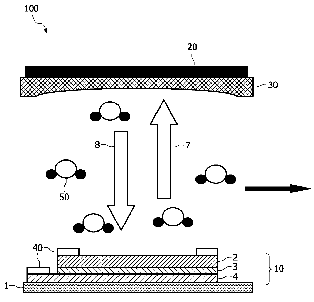
[0043] figure 1 Schematically shown is a laser sensor unit 100 comprising a vertical cavity surface emitting laser (VCSEL) having an active cavity 10 comprising a first reflective structure 4, e.g. A distributed Bragg reflector (DBR) of reflectivity; a second reflective structure 2, which is a DBR with a reflectivity of about 99%; and an active layer 3, such as a quantum well layer embedded between the two DBRs . The detector 20 is a photodiode attached to the first reflective structure 4 and to the substrate 1, which is a semiconductor substrate or any other substrate that can be used for this purpose. Electrodes 40 are attached to the DBRs to inject current into the active layer via the conductive DBRs. The current is used to electrically pump the active layer to emit a first light 7, which is laser light, through the second reflective structure 2 . Between the second reflective structure 2 and the diffusely scattering surface as optical feedback structure 30 there is a d...


PUM


Abstract

The present invention relates to a gas detection device (200) comprising a laser sensor unit (100). The laser sensor unit (100) is adapted to emit laser light being adapted to be at least partially absorbed by a gas to be detected (50). The laser sensor unit (100) is further adapted to generate measurement data based on self-mixing- interference (SMI) in an active cavity (10) of the laser sensor unit (100). The measurement data is influenced by the absorption of laser light by the gas to be detected, and an analyzer circuit (120) is provided to determine the presence and / or concentration of the gas to be detected (50), based on the measurement data received from the laser sensor unit (100).

Description

technical field [0001] The invention relates to a gas detection device comprising a laser sensor unit, a control system comprising such a gas detection device and a vehicle comprising such a control system. [0002] The invention also relates to a corresponding method for detecting the presence and / or concentration of a gas. Background technique [0003] The application of vertical cavity surface emitting lasers (VCSELs) for laser gas absorption spectroscopy is known from patent WO2005026705. The device described in WO2005026705 comprises at least two VCSEL diodes and two external photodetectors. VCSEL injection currents are at frequencies F and 2 F down modulation. The concentration of absorbed gas is detected by two lock-in amplifiers. [0004] This equipment is complex and expensive. Contents of the invention [0005] It is an object of the present invention to provide an improved gas detection device. [0006] This object is achieved by means of a gas detection ...

Claims


Application Information

Patent Timeline
Patent Type & Authority Applications(China)
IPC IPC(8): G01N21/45G01N21/39G01J3/433G08B17/103F23N5/00H01S5/183H01S5/187G08B17/117
CPCF23N5/082G01N21/39G01N21/3504G01N2021/399G01N21/359H01S5/183G01N21/0332G01N2021/451H01S5/14G01N2021/8416G01N21/45F23N5/242H01S5/0656G01J3/4338G01J3/433F23N5/00
Inventor M.韩A.克劳斯
Owner KONINKLIJKE PHILIPS ELECTRONICS NV
Why Eureka
Try Eureka