Water-circulating heat radiating pad

A heat dissipation pad and water circulation technology, applied in the field of functional pads, can solve the problems of high cost, troublesome installation, and inability to popularize and apply, and achieve the effects of easy portability and installation, obvious heat dissipation effect, and improved driving environment

Inactive Publication Date: 2011-06-15
张吉俊 +1
View PDF12 Cites 5 Cited by
  • Summary
  • Abstract
  • Description
  • Claims
  • Application Information

AI Technical Summary

Problems solved by technology

The disadvantage of this patent is that the actual temperature of the external environment of the car is too high, and it is impossible to cool it to the required temperature by the external circulation of the car. Air conditioner cooling pipeline, firstly, it is troublesome to install, and secondly, it cannot solve the problem of not being able to turn on the air conditioner
[0004] Chinese patent CN2223045 discloses a temperature-regulating pad. The electric heating rod is installed in the water tank under the pad, which is suitable for winter; although the description mentions that in summer, only the submersible pump needs to be turned on to drive the water in the water tank and the pipeline in the pad to realize circulation. The effect of cooling can be achieved, but it is not difficult to see that when the patent is used in summer, because the water tank has no cooling measures, it can be expected that the cooling effec

Method used


Image

  • Water-circulating heat radiating pad
  • Water-circulating heat radiating pad
  • Water-circulating heat radiating pad

Examples


Embodiment 1

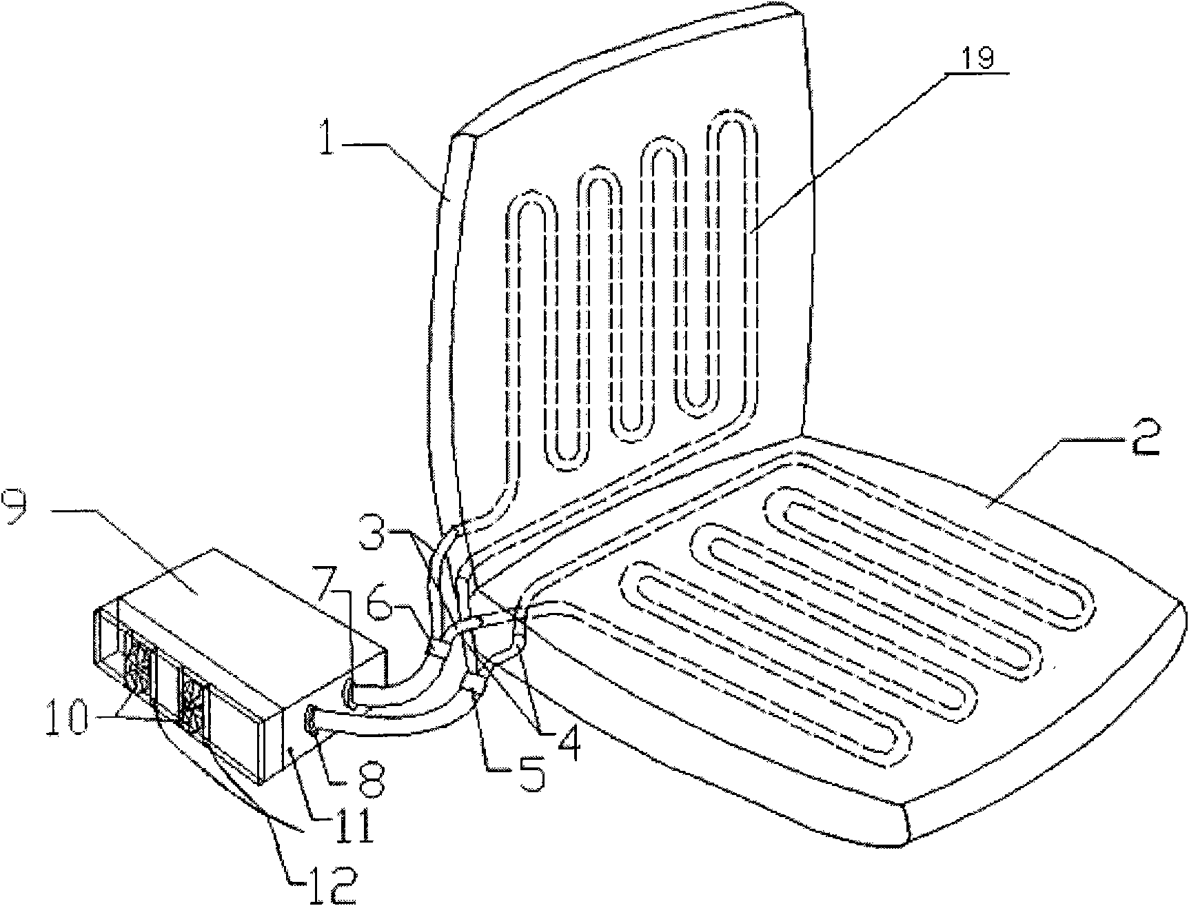
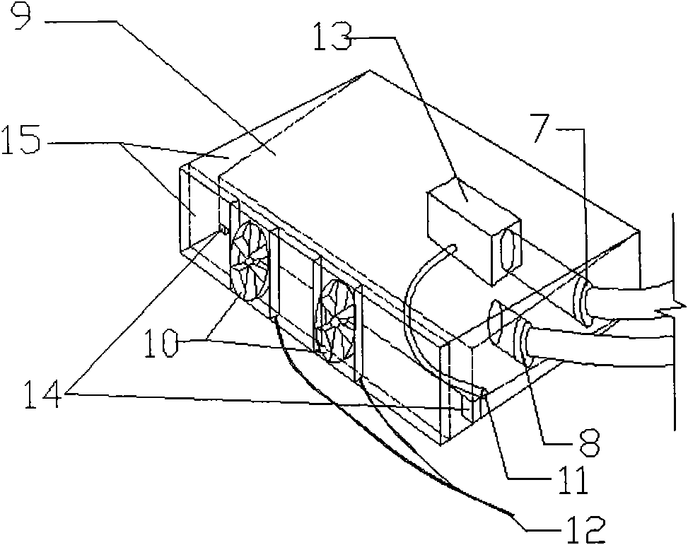
[0022] A water circulation heat dissipation pad, including mats 1, 2, Unicom waterway 19, water tank 9 and fan 10, said mats 1, 2 are pressed by two layers of waterproof cloth, and Unicom waterway 19 is formed therebetween, and water pump is arranged in the water tank 9 13. The water outlet 7 of the water pump 13 is connected to the water inlet 3 of the Unicom waterway 19, and the water outlet 4 of the Unicom waterway 19 is connected to the water inlet 8 of the water tank. A bracket 15 is arranged outside the water tank, and the fan 10 is arranged on the bracket 15 . The two sides of the water tank are trapezoidal, the top and bottom of the water tank are inclined relative to the horizontal plane, and a support frame is arranged between the bottom of the water tank and the support.

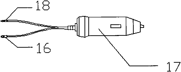
[0023] The power line connectors 11, 12 of the water pump 13 and the fan 10 are respectively connected to the automobile power supply 16, 18 through the cigarette lighter plug 17. It is convenien...

Embodiment 2

[0027] The power line connectors 11 and 12 of the water pump 13 and the fan 10 are respectively connected to a 220V power supply through an AC-DC current-voltage converter. The convenient pad can be used anywhere, without geographical restrictions, and it is convenient for patients with mobility issues to avoid other complications.


PUM


Abstract

The invention discloses a water-circulating heat radiating pad which comprises a pad, a communicating water path, a water tank and a fan, wherein a water pump is arranged in the water tank. The water-circulating heat radiating pad is characterized in that the pad is formed by pressing two layers of waterproof cloth, the communicating water path is formed between the two layers of waterproof cloth, a water outlet of the water pump is connected with a water inlet of the communicating water path, a water outlet of the communicating water path is connected with a water inlet of the water tank, and the fan is arranged at one side of the water tank. Water is filled in the communicating water path and the water tank, the water in the communicating water path and the water in the water tank are enabled to forcedly circulate by using the water pump, the heat radiated from the small of the back and the hip of people is taken away through water circulation; and heat of hot water circulating to the water tank is forcedly radiated by using the fan, the water subjected to the heat radiation flows through the communicating water path for dispelling heat air for people, therefore, the purposes of cooling and comforting are achieved.

Description

technical field [0001] The invention relates to a water circulation cooling pad, which belongs to the field of functional pads. Background technique [0002] People generally like to select the better cushion or mattress of heat dissipation function in summer, but the heat dissipation function of cushion or mattress in summer is all relatively poor, and can not well satisfy people's needs. For example, a driver who drives for a long time uses a seat cushion with poor heat dissipation effect, which hinders the heat dissipation of the waist, back, and buttocks, causing the corresponding parts to sweat and sweat, which affects the comfort of the driver while driving and increases unsafe factors. Another example is that patients who have been bedridden for a long time, because they cannot move or turn over, sweat easily under the patient's body, which will cause diseases such as bedsores after a long time. [0003] Chinese patent CN2170034 discloses an air-cooled liquid seat cu...

Claims


Application Information

Patent Timeline
IPC IPC(8): A47C7/74A47C27/00
Inventor 张士勇张吉俊张心爽张悦刘东民
Owner 张吉俊
Why Eureka
Try Eureka