Jet automatic back flush filter
A backwash and filter technology, applied in the field of water treatment, achieves the effects of low operating energy consumption, simplified automatic control system, and convenient installation and use
- Summary
- Abstract
- Description
- Claims
- Application Information
AI Technical Summary
Problems solved by technology
Method used
Image


Examples
Embodiment 1
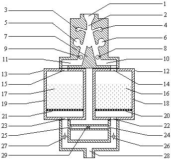
[0018] refer to figure 1 . The jet element consists of water flow input port 1, nozzle 2, left control hole 3, right control hole 4, left emptying hole 5, right emptying hole 6, splitter 7, right signal hole 8, left signal hole 9, right output channel 10. The left output channel 11 is formed. The splitter 7 divides the flow channel into a right output channel 10 and a left output channel 11. The left signal hole 9 and the left control hole 3 are connected to form the left signal channel through pipes from the outside. The left emptying hole 5 is on the left side of the left output channel 11. On the wall, it communicates with the left output channel 11 and is connected to a sewage pipe from the outside; the right signal hole 8 and the right control hole 4 are connected to form the right signal channel through the external part of the pipeline, and the right emptying hole 6 is on the left side of the right output channel 10 On the side wall, it communicates with the right out...
Embodiment 2
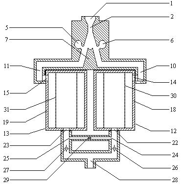
[0023] A jet automatic backwashing filter shown in Example 2 has similar basic structural features to that of Example 1, the difference is that the jet element cancels the signal channel, the filter medium is a filter screen, and the filter screen is arranged inside the filter assembly shell to filter Between the water inlet of the component and the water outlet of the filter component.
[0024] refer to figure 2 . The jet element is composed of a water flow input port 1, a nozzle 2, a left emptying hole 5, a right emptying hole 6, a splitter 7, a right output channel 10, and a left output channel 11. The splitter 7 divides the flow channel into a right output channel 10 and a left output channel 11; the left emptying hole 5 is on the left side wall surface of the left output channel 11, communicates with the left output channel 11, and connects a blowdown pipe from the outside; The emptying hole 6 communicates with the right output channel 10 on the left side wall surface ...
PUM
 Abstract
Description
Claims
Application Information
 - R&D
- Intellectual Property
- Life Sciences
- Materials
- Tech Scout
- Unparalleled Data Quality
- Higher Quality Content
- 60% Fewer Hallucinations
Browse by: Latest US Patents, China's latest patents, Technical Efficacy Thesaurus, Application Domain, Technology Topic, Popular Technical Reports.
© 2025 PatSnap. All rights reserved.Legal|Privacy policy|Modern Slavery Act Transparency Statement|Sitemap|About US| Contact US: help@patsnap.com