Jet self-cleaning screen filter

A self-cleaning and filter technology, applied in the field of water treatment, can solve the problems of high equipment cost and complex self-cleaning control system of filters, and achieve the effects of low manufacturing cost, simplified automatic control system, and simple operation and maintenance

Inactive Publication Date: 2013-07-17
JIANGSU UNIV
View PDF7 Cites 0 Cited by
  • Summary
  • Abstract
  • Description
  • Claims
  • Application Information

AI Technical Summary

Problems solved by technology

Due to the installation of automatic control devices such as differential pressure sensors, controllers, and electric sewage valves, the filter has a complex self-cleaning control system and high equipment cost, and requires professional and technical personnel with automatic control knowledge for daily maintenance and operation.
Application No. 200510048198.1 of the Chinese Patent "Automatic Recoil Filter for Micro-irrigation", Chinese Patent Application No. 02119415.7 of "Fully Automatic Self-Cleaning Continuous Water Filter", Application No. 02119415.7 of the Chinese Patent "Micro-irrigation Horizontal "Spiral self-cleaning mesh filter" discloses a rotary suction type self-cleaning filter mesh filter, which sucks out the dirt in the filter mesh through the suction pipe to realize the self-cleaning of the filter mesh without stopping the machine, but it needs to be manually or manually cleaned. The automatic control device realizes the self-cleaning of the filter screen

Method used


Image

  • Jet self-cleaning screen filter
  • Jet self-cleaning screen filter
  • Jet self-cleaning screen filter

Examples


Embodiment 1

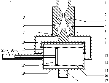
[0021] refer to figure 1 and figure 2 . The jet element consists of water flow input port 1, nozzle 2, control hole Ⅰ3, control hole Ⅱ4, emptying hole Ⅰ5, emptying hole Ⅱ6, signal hole Ⅰ7, signal hole Ⅱ8, splitter 9, output channel Ⅰ10, output channel Ⅱ11, Among them, the flow splitter 9 divides the flow channel into the output channel I10 and the output channel II11, the signal hole I7 and the control hole I3 are connected from the outside through the pipe to form the signal channel I, and the emptying hole I5 is on the left side wall of the output channel I10. The channel I10 is connected, and communicates with the sewage channel 21 from the outside through the pipeline; the signal hole II8 is connected with the control hole II4 through the external part of the pipeline to form the signal channel II, and the emptying hole II6 is on the right side wall of the output channel II11, and is connected with the output channel II. II11 communicates, and communicates with the sewa...

Embodiment 2

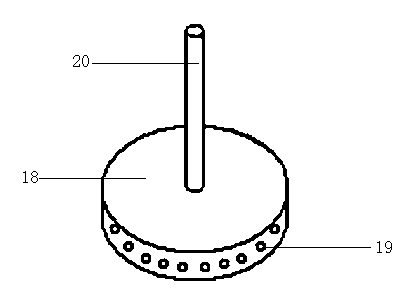
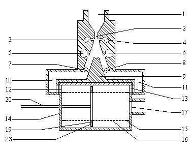
[0024] A jet self-cleaning screen filter shown in Example 2 has similar basic structural features to that of Example 1, the difference is that the sewage suction component is composed of a hollow circular thin cylinder and a sewage pipe, and the sewage suction holes are arranged on the circular column On the inner circumference of the body, more than two sewage pipes can be set and connected vertically to the bottom surface of the ring; the sewage suction assembly is outside the filter screen; the water inlet of the filter assembly is outside the filter screen, and the outlet of the filter assembly is on the outside of the filter screen Inside: The turbid water enters from the outside of the filter, and after being filtered by the filter, the clean water flows out from the inside of the filter.

[0025] refer to image 3 and Figure 4 . The jet element consists of water flow input port 1, nozzle 2, control hole Ⅰ3, control hole Ⅱ4, emptying hole Ⅰ5, emptying hole Ⅱ6, signal ...

Embodiment 3

[0029] A jet self-cleaning screen filter shown in Example 3 has similar basic structural features to that of Example 1, the difference being that the emptying hole of the jet element is canceled; the filter assembly water inlet is arranged on the side of the filter assembly housing; the sewage discharge A water wheel 22 is installed at the tail end of the pipe 20, so that the blowdown assembly rotates while moving longitudinally.

[0030] refer to Figure 5 . The jet element is composed of water flow input port 1, nozzle 2, control hole I3, control hole II4, signal hole I7, signal hole II8, splitter 9, output channel I10, and output channel II11. The splitter 9 divides the flow channel into output channel I10 and output channel II11, the signal hole I7 is connected with the control hole I3 to form the signal channel I, and the signal hole II8 is connected to the control hole II4 to form the signal channel II.

[0031] The filter assembly is composed of the filter assembly wa...


PUM


Abstract

The invention relates to a jet self-cleaning screen filter. The filter consists of a jet element, a screen filtering component and a dirt sucking component, wherein two water inlets of the filtering component are formed on the two sides of a hollow thin cylinder of the dirt sucking component and are connected with two output ends of the jet element respectively; and the water outlet of the filtering component is connected with a water delivery pipeline. Differential pressure formed by the blockage of a filter screen drives the wall attachment and reversing of jet to push the dirt sucking component to do cyclic reciprocating motion, so that obstructions aggregated on the filter screen are sucked and discharged, and the self-cleaning process of the filter screen is realized; the dirt sucking component is automatically operated and reversed by the jet; a reversing mechanism is durable and reliable; and the filter has a simple structure, is convenient to install and use, can automaticallyclean the filter screen in a working state, can continuously work and is suitable for filtering micro-irrigation, spray irrigation, low-pressure pipeline irrigation water and industrial circulating and cooling water.

Description

technical field [0001] The invention belongs to the technical field of water treatment and relates to water filtering equipment, in particular to a jet self-cleaning screen filter. Background technique [0002] Self-cleaning mesh filter is the most widely used filter equipment in agricultural micro-irrigation system and industrial water treatment. At present, the common sewage suction self-cleaning mesh filter is equipped with automatic control devices such as differential pressure sensor, controller, electric sewage valve, etc. There is a rotating frame inside the filter, which is generally driven by a motor or a hydraulic motor. The part close to the filter screen is provided with a sewage suction port. When the controller monitors that the pressure difference between the inside and outside of the filter screen reaches the preset value, it starts the electric sewage valve and the driving device, drives the rotating frame to rotate, and sucks and discharges the blockages a...

Claims


Application Information

Patent Timeline
Patent Type & Authority Patents(China)
IPC IPC(8): B01D29/35B01D29/62
Inventor 王新坤袁寿其李红朱兴业
Owner JIANGSU UNIV
Why Eureka
Try Eureka