Single-control opening and closing synchronous valve set and water treatment system thereof

A water treatment system and valve group technology, applied in the field of water treatment, can solve the problems of high price, affecting the operation of the filter tank, complex structure of the tank body, etc., achieving long service life, reducing equipment investment and maintenance management costs, and reducing equipment failures rate effect

Pending Publication Date: 2020-11-24
HUNAN ARCHITECTURAL DESIGN INST
View PDF0 Cites 0 Cited by
  • Summary
  • Abstract
  • Description
  • Claims
  • Application Information

AI Technical Summary

Problems solved by technology

Filtration is mainly to intercept pollutants in water through fillers to achieve the purpose of water purification. After a period of time, the filter system needs to flush and discharge the fillers. In previous projects, traditional filters and control methods were used, not only the structure of the pool was complicated , it is also necessary to use expensive electric water outlet valves and drain valves, and the control system needs to close the water outlet valves and open the drain valves to realize its functions. If the control system fails, it will affect the operation of the filter

Method used


Image

  • Single-control opening and closing synchronous valve set and water treatment system thereof
  • Single-control opening and closing synchronous valve set and water treatment system thereof
  • Single-control opening and closing synchronous valve set and water treatment system thereof

Examples


Embodiment 1

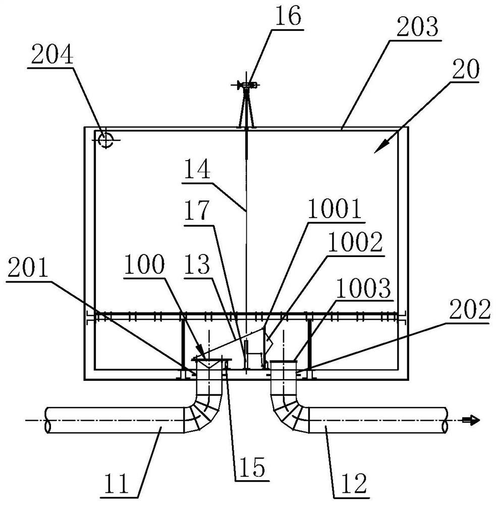
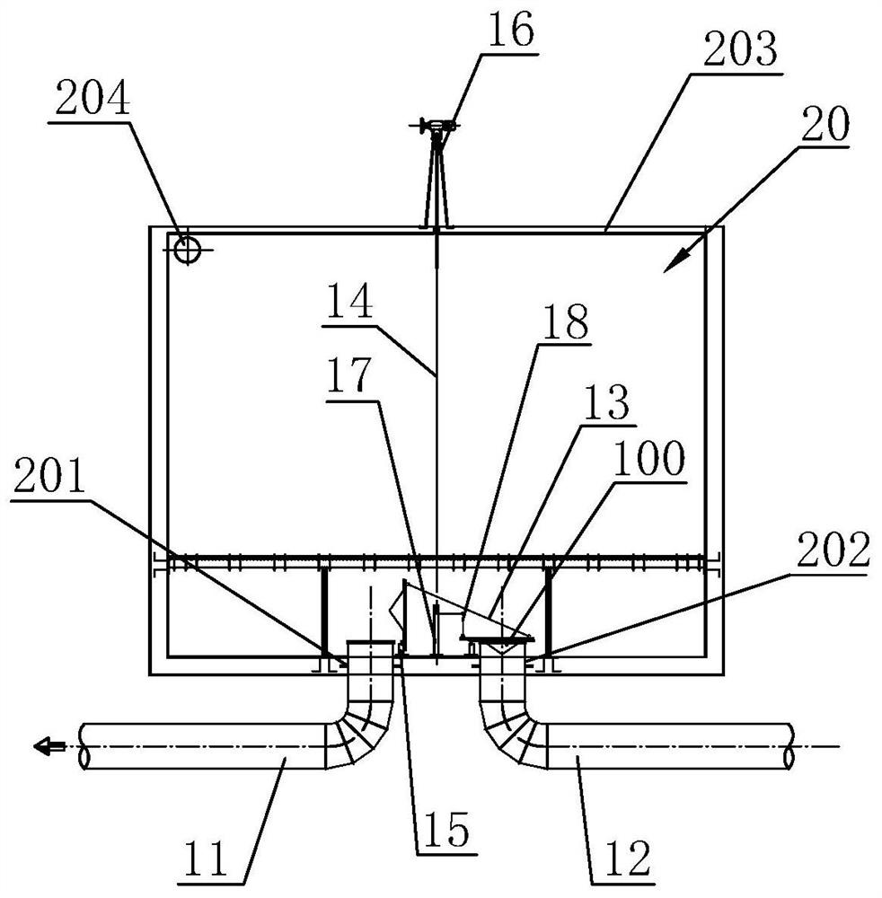
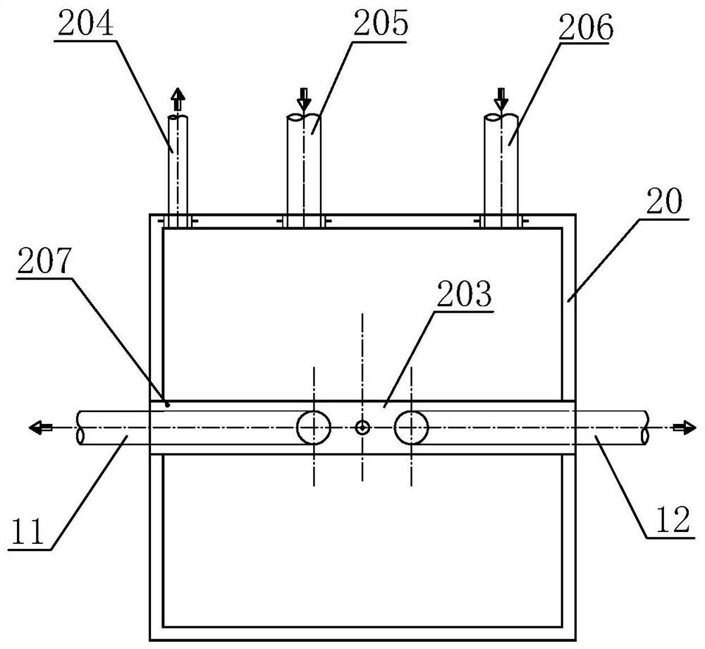
[0027] see figure 1 , image 3 or figure 2 , image 3 , the present embodiment provides a synchronous valve group of single-control one-on-one-off, including a first pipe 11 , a second pipe 12 , a valve group, a push-pull rod 13 and a control rod 14 .

[0028] The valve group includes two valves 100 with the same structure, and the two valves 100 are reversibly arranged on the opposite inner sides of the first pipeline 11 and the second pipeline 12 through hinge seats 15, so that the valves can be opposite to the first pipeline. The first pipeline and the second pipeline are opened and closed to open or close the pipelines.

[0029] Specifically, the valve 100 of this embodiment includes a valve plate 1001 and a hole recognition cone 1002. The hole recognition cone 1002 is arranged at the bottom of the valve plate 1001 and can be accommodated in the first pipe 11 or the first pipe 11. Two pipelines 12, one end of the valve plate 1001 is hinged with the hinge seat 15, as ...

Embodiment 2

[0034] In this embodiment, the valve is further designed on the basis of Embodiment 1. In order to ensure the sealing effect of the valve when it is closed, the valve 100 in this embodiment also includes an annular valve seat 1003, such as figure 1 or figure 2 As shown, the annular valve seat 1003 snaps into the edge of the mouth of the first pipe 11 or the second pipe 12 .

[0035] Preferably, the annular valve seat 1003 is a valve seat wrapped with a rubber ring, and the annular valve seat 1003 is made of Q235 material.

[0036] Preferably, the valve plate 1001 is a valve plate wrapped with a rubber pad, and the valve plate 1001 is made of S304 stainless steel.

[0037] Preferably, the hole recognition cone 1002 is integrally formed with the valve plate 1001 , and the integrally formed structure has higher structural strength.

[0038] This embodiment adopts the valve seat made of Q235 material, so that the valve plate of the valve can avoid the direct impact of the valve...

Embodiment 3

[0040]On the basis of Embodiment 1 or Embodiment 2, the top of the control rod 14 in this embodiment is connected with an electric or manual or electric-manual dual-purpose hoist 16, and an electric and manual dual-purpose hoist 16 is preferably used. The gate hoist can cooperate with the PLC controller and the filter system of the filter pool to realize automatic control of the opening / closing switching of the two valves. Compared with the traditional electric water outlet valve and drain valve, the automatic control system is greatly simplified and the Equipment failure rate.


PUM


Abstract

The invention relates to a single-control opening and closing synchronous valve set. The valve set comprises a first pipeline, a second pipeline, a valve set body, a push-pull rod and a control rod, the valve set body comprises two valves of the same structure, and the two valves are arranged on the opposite inner sides of the first pipeline and the second pipeline in an overturning mode through hinge seats correspondingly; each valve comprises a valve plate and a hole recognizing cone, the hole recognizing cones are arranged at the bottoms of the valve plates and can be contained in the firstpipeline or the second pipeline, and one ends of the valve plates are hinged to the hinge seats; the two ends of the push-pull rod are hinged to the ends, away from the hinge seats, of the two valvescorrespondingly, and the length of the push-pull rod meets the requirement that the two valves are in an open state and a closed state; and the control rod is arranged between the first pipeline andthe second pipeline, and the bottom of the control rod is hinged to the end, close to the hinge seat, of the valve plate of one valve. According to the valve set, a filtered water outlet valve, a flushing water drainage valve and a control program thereof are simplified, an automatic control system is simplified, and the equipment failure rate is reduced.

Description

technical field [0001] The invention relates to the technical field of water treatment, in particular to a single-control one-on-one-off synchronous valve group and a water treatment system thereof. Background technique [0002] In the field of initial rainwater, black and odorous water treatment, and artificial rapid infiltration of sewage, filtration technology is often used according to different water treatment requirements. Filtration is mainly to intercept pollutants in water through fillers to achieve the purpose of water purification. After a period of time, the filter system needs to flush and discharge the fillers. In previous projects, traditional filters and control methods were used, not only the structure of the pool was complicated , It is also necessary to use expensive electric water outlet valves and drain valves, and the control system needs to close the water outlet valves and open the drain valves to realize its functions. If the control system fails, it...

Claims


Application Information

Patent Timeline
Patent Type & Authority Applications(China)
IPC IPC(8): F16K1/20F16K1/36F16K1/32F16K27/02F16K31/60F16K31/02
CPCF16K1/20F16K1/32F16K1/36F16K27/0209F16K31/02F16K31/60
Inventor 王梅强刘安安
Owner HUNAN ARCHITECTURAL DESIGN INST
Why Eureka
Try Eureka