
Method for improving conductive nozzle of submerged arc automatic welder and welding rotating stand shaft

A submerged arc automatic welding machine and contact tip technology, which is applied in arc welding equipment, electrode accessories, welding rod characteristics, etc., can solve the problem of unreachable welding wire, reduce welding volume, control welding deformation, and reduce welding cost and processing cost. Effect

Active Publication Date: 2011-06-15
CITIC HEAVY INDUSTRIES CO LTD
View PDF5 Cites 3 Cited by
  • Summary
  • Abstract
  • Description
  • Claims
  • Application Information

AI Technical Summary

Problems solved by technology

[0013] In order to solve the problem that the head of the submerged arc automatic welding machine and the rigid straight cylindrical contact tip may interfere with the welding part of the turret shaft, so that the welding wire cannot reach the welding position of the groove, the invention provides an improved submerged arc automatic welding The contact tip of the machine is used for the welding method of the turret shaft. In this welding method, the rigid straight cylindrical contact tip is changed into a fixed contact tip and a movable contact tip, and the movable contact tip is centered on the On the single U-shaped annular groove of the turret shaft, use other welding characteristics of the submerged arc automatic welding machine to better control the weld quality of the turret shaft, reduce the repair rate of the turret shaft weld and reduce welding deformation In the end, the welding size of the turret shaft is also reduced accordingly, which reduces the welding cost and processing cost

Method used


Image

  • Method for improving conductive nozzle of submerged arc automatic welder and welding rotating stand shaft
  • Method for improving conductive nozzle of submerged arc automatic welder and welding rotating stand shaft
  • Method for improving conductive nozzle of submerged arc automatic welder and welding rotating stand shaft

Examples


Embodiment Construction

[0030] Take the turret shaft of the ZZDP1250A planetary gear reducer as an example.

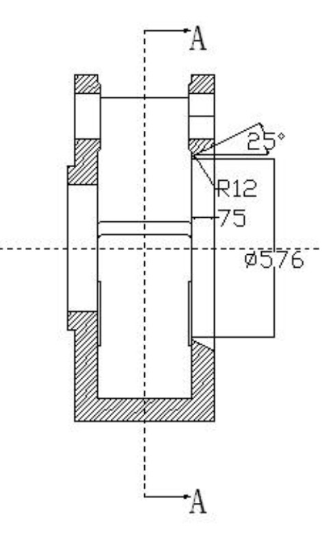
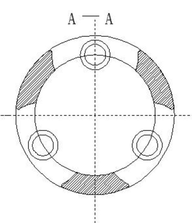
[0031] combine Figure 1-2 , the material of the turret shaft body is ZG35CrMo, the maximum outer diameter is Φ1120mm, and the width is 452mm. The diameter of the positioning hole of the turret shaft body at the single U-shaped annular groove is Φ576mm, and the depth of the U-shaped groove is 79mm (with a machining allowance of 6mm). , U-shaped groove fillet R12mm, U-shaped groove angle 25°, U-shaped groove bottom stop depth 2mm (U-shaped groove bottom stop 2mm+ U-shaped groove design depth 73mm=75mm is the design width) .

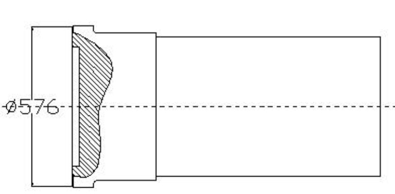
[0032] combine image 3 ,The material of the turret shaft head is 35CrMo, the total length is 1111mm, the diameter of the T-joint is Φ576mm, the width of the T-joint is 79mm (with a machining allowance of 6mm), and the depth of the bottom of the T-joint is 2mm. The machining allowance of the turret shaft body and the turret shaft head is 6mm on one side.

[0033] Befor...


PUM


Abstract

The invention discloses a method for improving a conductive nozzle of a submerged arc automatic welder and welding a rotating stand shaft, which comprises the following steps of: rigidly fixing a rotating stand shaft body (4) through a clamping jaw (5) of a rotary platform (6) before welding, arranging the T-shaped joint end of a rotating stand shaft head (1) into a positioning hole of the rotating stand shaft body, checking the coaxiality of the rotating stand shaft head, the rotating stand shaft body and the rotary platform by using a submerged arc automatic welder head (3) respectively, and performing spot welding and under coat welding sequentially; and clamping a fixed conductive nozzle on the submerged arc automatic welder head (3), connecting the fixed conductive nozzle and a movable conductive nozzle through a variable angle hinge frame and a flexible copper net arranged thereon, regulating the movable conductive nozzle to be aligned with a single U-shaped annular groove of the rotating stand shaft body (4), and performing submerged arc automatic welding after arc initiation, wherein the interlayer temperature of the layered submerged arc automatic welding of each lane is not less than 280 DEG C till the submerged arc automatic welder completes all layered lane welding processes. The submerged arc automatic welding is executed according to the specifications so as to shorten the welding period and improve the quality of seams.

Description

technical field [0001] The invention belongs to the field of welding technology, and in particular relates to an improved contact tip of a submerged arc automatic welding machine and a welding method for a turret shaft. Background technique [0002] Figure 1-2 It is a schematic diagram of the structure of the turret shaft, and the turret shaft is made of ZG35CrMo. image 3 It is a schematic diagram of the structure of the turret shaft head, and the turret shaft head is made of 35CrMo. The large end of the turret shaft head is installed at Φ576mm [0003] The turret shaft welded in the positioning hole of the turret shaft body, namely Φ576mm, constitutes the turret shaft used on the planetary gear reducer. The turret shaft after welding is required to be able to transmit a large torque. With its simple structure, lighter weight and lower material cost, the turret shaft is gradually being recognized by many domestic enterprises and widely used. [0004] According to the st...

Claims


Application Information

Patent Timeline
IPC IPC(8): B23K9/18B23K9/32B23K9/26
Inventor 权建军王丽宏侯小冲孙丽红
Owner CITIC HEAVY INDUSTRIES CO LTD
Learn More