Eureka AIR delivers breakthrough ideas for toughest innovation challenges, trusted by R&D personnel around the world.

Simple spot-welding robot mechanism

A robot and spot welding technology, which is applied in the direction of welding equipment, auxiliary welding equipment, welding/cutting auxiliary equipment, etc., can solve the problems of reducing the rigidity of the robot, large error accumulation, and large moment of inertia of the robot structure, and achieve low manufacturing costs. The effect of small cumulative errors in weight and work

Inactive Publication Date: 2014-08-06
GUANGXI UNIV
View PDF4 Cites 0 Cited by
  • Summary
  • Abstract
  • Description
  • Claims
  • Application Information

AI Technical Summary

Problems solved by technology

However, this side-mounted robot is a cantilever structure, which reduces the rigidity of the robot and is generally suitable for robots with small loads.
Traditional articulated welding robots need to install motors at the joints, which makes the robot structure have shortcomings such as large moment of inertia and large error accumulation.

Method used


Image

  • Simple spot-welding robot mechanism
  • Simple spot-welding robot mechanism
  • Simple spot-welding robot mechanism

Examples


Embodiment Construction

[0023] The technical solutions of the present invention will be further described below in conjunction with the accompanying drawings and embodiments.

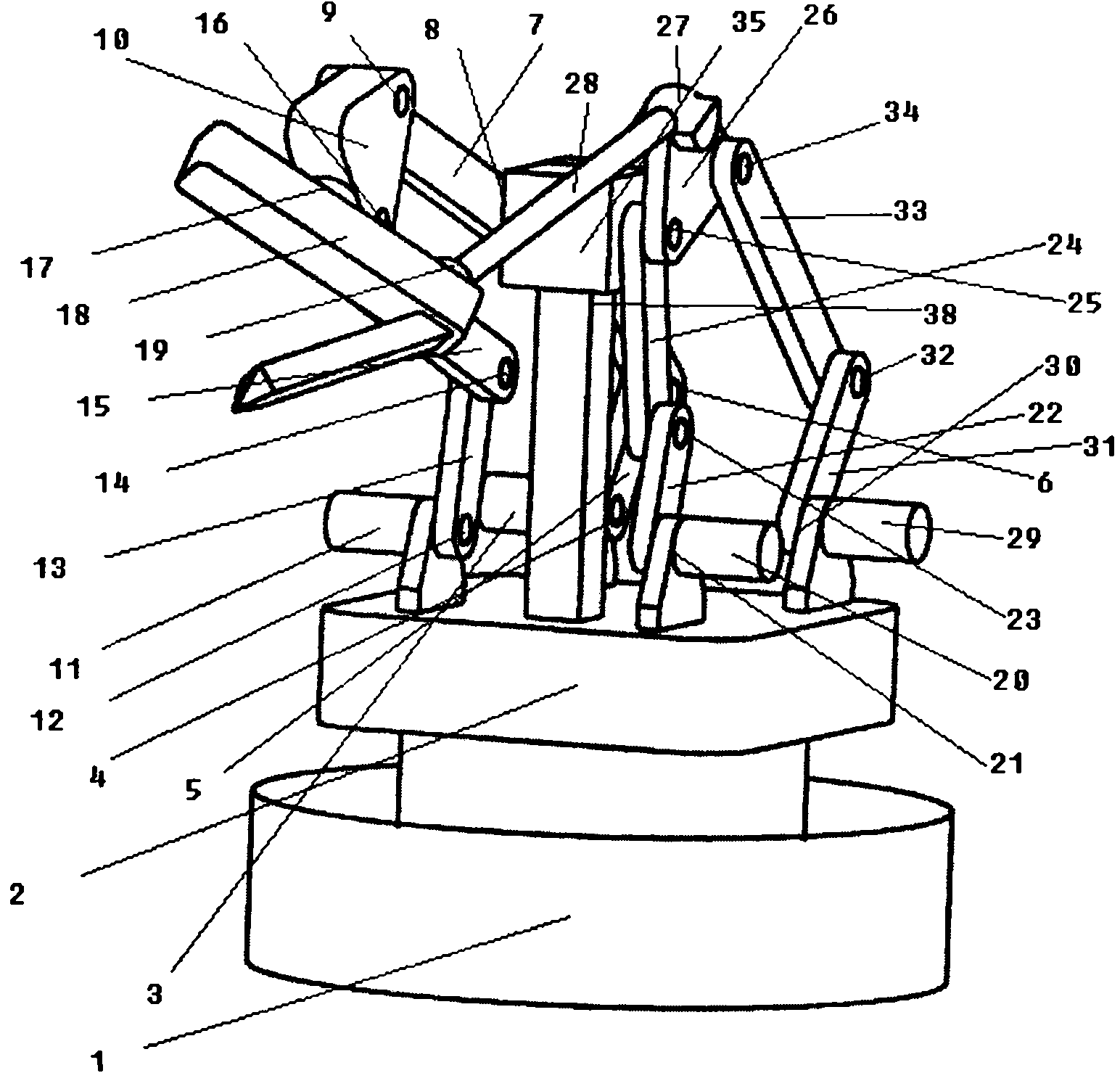
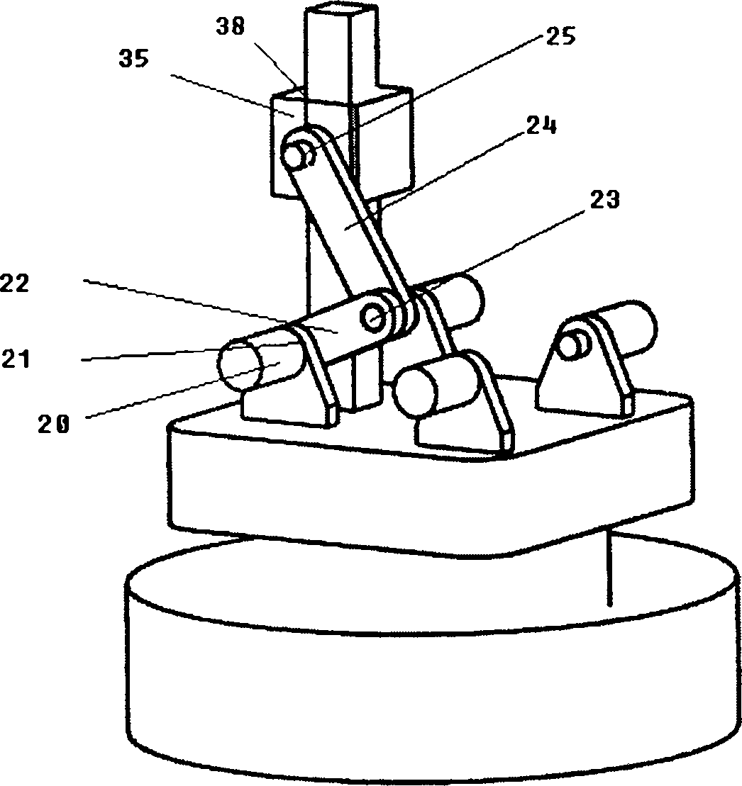
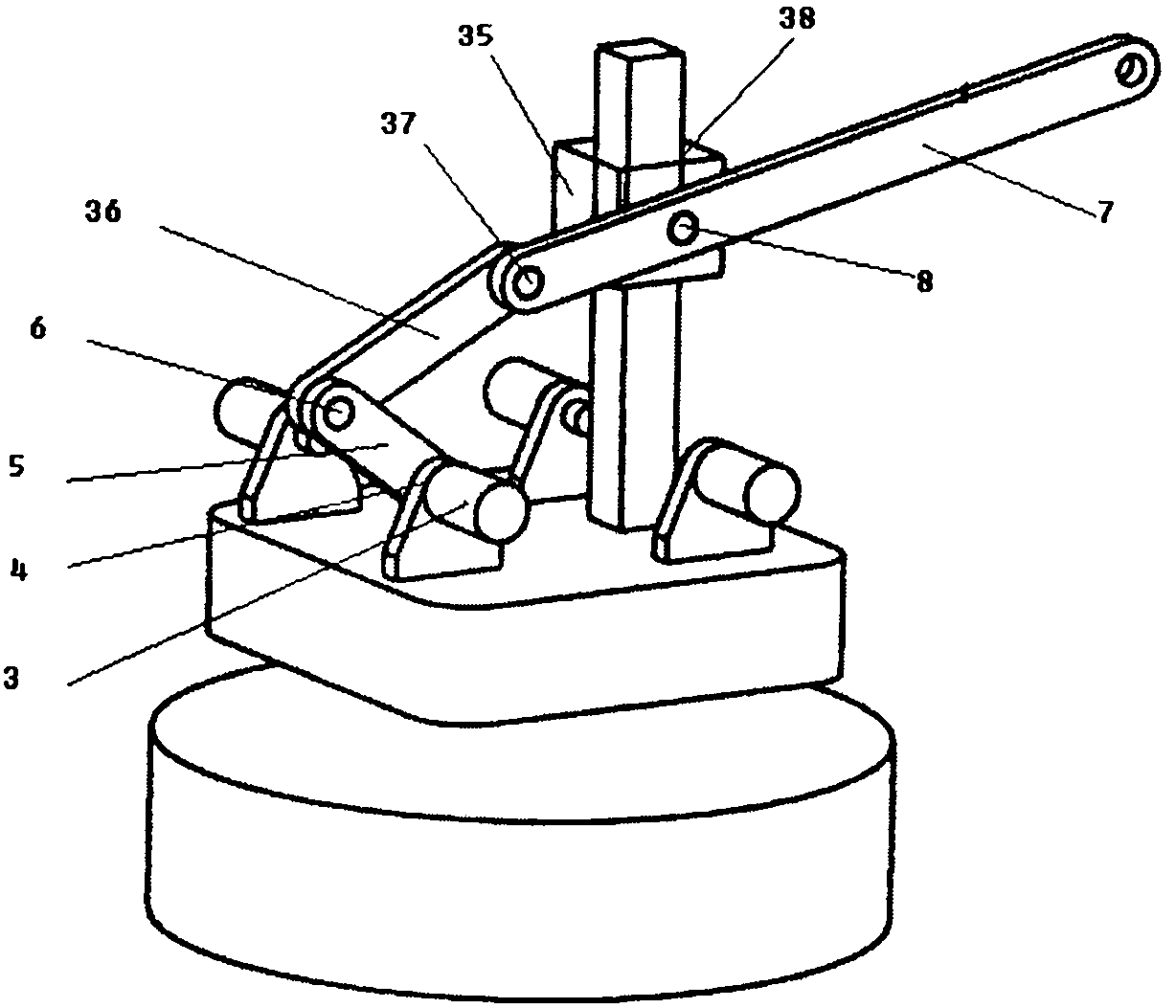
[0024] control figure 1 , 2 , 3, 4 and 5, a kind of simple and easy spot welding robot mechanism, comprise the first welding torch stand position adjustment mechanism, the second welding torch stand position adjustment mechanism, the first welding torch stand attitude adjustment mechanism, the second welding torch stand attitude adjustment mechanism, the welding torch stand and rack 2. The frame 2 can be installed on the rotary platform 1 to realize the five-degree-of-freedom movement of the entire robot space.

[0025] control figure 1 , 2 , the first welding torch frame position adjustment mechanism is formed by connecting the first servo motor 3, the first active rod 5, the first connecting rod 36, the second connecting rod 7, the slider 35, the swing frame 10 and the frame 2, One end of the first active rod 5 is conne...


PUM


Abstract

The invention relates to a simple spot-welding robot mechanism which comprises a first welding torch rack position adjusting mechanism, a first welding torch rack attitude adjusting mechanism, a second welding torch rack position adjusting mechanism, a second welding torch rack attitude adjusting mechanism, a welding torch rack and a stand, wherein the welding torch rack is composed of a swinging rack and a rotating rack, the swinging rack is connected with the rotating rack by a fourteenth rotating pair, the swinging rack is connected with the first welding torch rack position adjusting mechanism by a fifteenth rotating pair, the swinging rack is connected with the first welding torch rack attitude adjusting mechanism by a tenth rotating pair, the rotating rack is connected with the second welding torch rack attitude adjusting mechanism by a second spherical pair, and a welding torch is arranged on the rotating rack. The simple spot-welding robot mechanism provided by the invention is driven by external rotating pairs, and all servo motors are installed on the stand, therefore, the weight of working bar parts can be reduced effectively, the accurate positioning of the working bar parts can be realized, and the working efficiency of the working bar parts can be improved.

Description

technical field [0001] The invention relates to the field of industrial welding robots, in particular to a simple spot welding robot mechanism. Background technique [0002] Welding robots are industrial robots engaged in welding, including cutting and spraying. According to the definition of the International Organization for Standardization (ISO) industrial robot terminology standard, an industrial robot is a multipurpose, reprogrammable automatic control manipulator (Manipulator) with three or more programmable axes for industrial automation field. Spot welding does not place high demands on the robots used. Because spot welding only needs point control, there are no strict requirements for the moving track of the welding tongs between points. The welding robots produced in various countries in the world are basically articulated robots, and most of them have 6 axes. Among them, the 1, 2, and 3 axes can send the end tool to different spatial positions, while the 4, 5, ...

Claims


Application Information

Patent Timeline
Patent Type & Authority Patents(China)
IPC IPC(8): B23K37/02B23K37/00
Inventor 蔡敢为王红州潘宇晨陈渊张林温芳李岩舟苏文桂王汝贵
Owner GUANGXI UNIV
Why Eureka
Eureka Blog
Learn More