

Variable compression ratio engine
A compression ratio and engine technology, applied in engine control, machine/engine, mechanical equipment, etc., can solve the problems of large round-trip mass, no mass production, high cost, etc., to improve intake charge, save fuel, and structure simple effect
Inactive Publication Date: 2011-06-15
高伟
View PDF5 Cites 3 Cited by
- Summary
- Abstract
- Description
- Claims
- Application Information
AI Technical Summary
Problems solved by technology
The French MCE-5 engine also because of its innovative structure makes its round-trip mass and volume too large, difficult to install, and high in cost
The above two variable compression ratio engines were not mass-produced due to certain defects.
Method used
View moreImage
Smart ImageViewing Examples

Examples
Embodiment Construction
Login to View More PUM
 Abstract
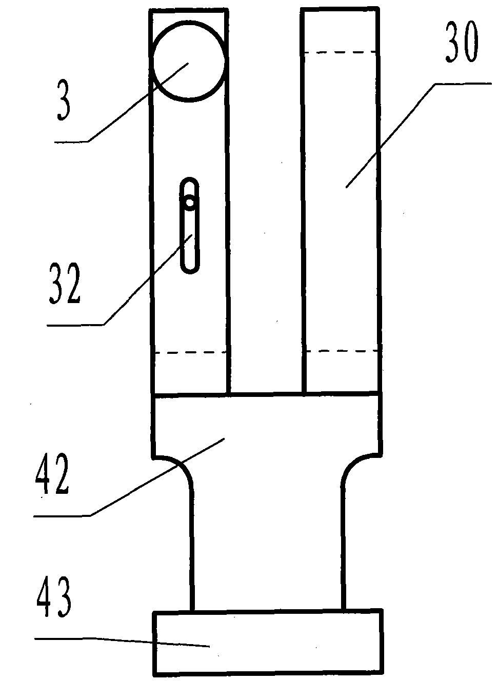
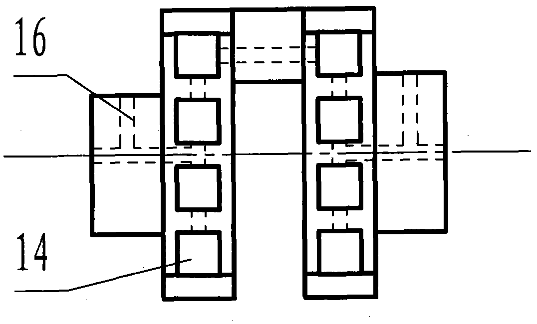
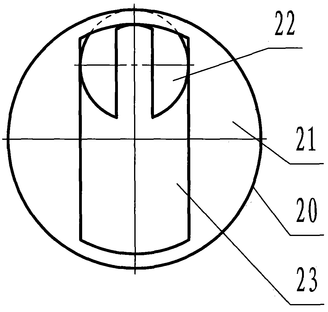
The invention discloses a variable compression ratio engine which comprises an ECU (electronic control unit), a compression ratio sensor, a crank shaft, a connecting rod, a piston and the like, wherein crank shaft sleeves are sleeved on the crank shaft; one end of the connecting rod is rotatably connected with a neck bush, and the other end of the connecting rod is connected with the piston through a piston pin; two crank sleeves on each group of crank shaft sleeves are respectively installed in the manipulation holes of two manipulation sleeves; the crank shaft sleeves are controlled through regulating the manipulation sleeves; and the distance between a main journal and the neck bush is changed when the piston is at the top dead center though the upward or downward motion of the crank shaft sleeves along the central line of a cylinder body, thereby changing different compression heights when the piston is at the top dead center to realize different compression ratios. By adopting the technical scheme provided by the invention, the control can be carried out according to the air inlet charge and various loading working conditions as well as different compression ratios required by various fuels, so that the compression ratio of the motor is mostly matched with the current condition to achieve the optimum effect of fuel economy, dynamic property and emission, and the selections of fuel materials for one motor are wider.
Description
variable compression ratio engine technical field The invention relates to the variable compression ratio technology of the engine, which can realize different compression ratios by controlling the different compression heights of the piston at the top dead center. technical background The present invention belongs to the optimized version of my published invention patent "Variable Volume Compression Ratio Engine" with application number 2010102351061. At present, in order to protect the environment and reduce greenhouse gas emissions, major automobile manufacturers are developing new energy vehicles such as electric vehicles, hydrogen-powered vehicles, and hybrid vehicles. Although electric vehicles have zero emissions, they have inherent defects in terms of power and mileage. The battery takes up a lot of space and is expensive. When an accident occurs, the battery is easily short-circuited and will cause secondary damage to the owner. Although hydrogen-powered vehicles...
Claims
Login to View More Application Information
Patent Timeline
 Patent Type & AuthorityApplications(China)
IPC IPC(8): F02D15/04
Inventor高伟
Owner高伟