Relay light-amplified laser ranging method and device for cooperative target

A cooperative target, laser ranging technology, applied in the field of space measurement, can solve the problems of human eye safety and target damage, high cost, and difficult improvement, and achieve the effect of avoiding human eye safety and device damage, reducing requirements, and reducing costs.

Active Publication Date: 2011-06-15
CHONGQING UNIV OF POSTS & TELECOMM
View PDF5 Cites 25 Cited by
  • Summary
  • Abstract
  • Description
  • Claims
  • Application Information

AI Technical Summary

Problems solved by technology

If other conditions remain the same, every time the measurement distance is doubled, the emitted laser power needs to be increased to 16 times, and increasing the emitted laser power also faces dangers such as human eye safety and target damage.
In additio

Method used


Image

  • Relay light-amplified laser ranging method and device for cooperative target
  • Relay light-amplified laser ranging method and device for cooperative target
  • Relay light-amplified laser ranging method and device for cooperative target

Examples


Embodiment Construction

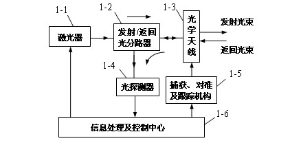
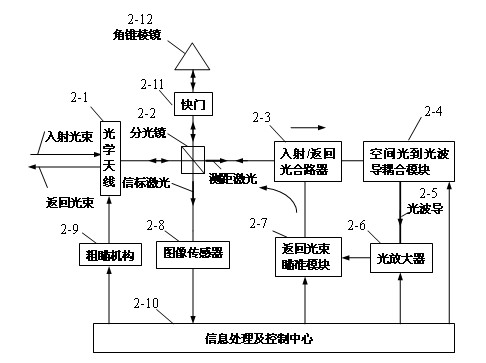
[0025] The cooperative target laser ranging device of the present invention includes two parts: a distance measuring station and a cooperative target device. Such as figure 1 is a schematic diagram of the distance measuring station structure, such as figure 2 It is a schematic diagram of the cooperation target structure.

[0026] The implementation of the present invention will be specifically described below with reference to the accompanying drawings and specific examples,

[0027] In this implementation case, the beacon laser and the ranging laser use the same laser signal. The ranging station includes information processing and control center (1-6), acquisition, alignment and tracking mechanism (1-5), optical antenna (1-3), laser (1-1), launch / return optical splitter (1-2), light detectors (1-4).

[0028] The cooperative target device under test consists of an optical antenna (2-1), a beam splitter (2-2), an image sensor (2-8), a spatial light-to-optical waveguide cou...


PUM


Abstract

The invention relates to a relay light-amplified laser ranging method and a relay light-amplified laser ranging device for a cooperative target, which are characterized in that: a ranging laser signal which is incident to the cooperative target is subjected to relay light amplification by using a light amplifier, and the amplified light signal is returned to a ranging station, wherein the cooperative target consists of an information processing and control center, a coarse sighting mechanism, an optical antenna, a spectroscope, an image sensor, a space light-to-light waveguide coupling module, an optical waveguide, the light amplifier, a return light beam sighting module, a light incidence/return combiner, a pyramid prism and a shutter. By the laser ranging method and the laser ranging device for the cooperative target, the defect of insufficiency in transmitted laser power during remote laser ranging can be overcome, the required laser power is quadratisch of distance instead of biquadrate of the distance, and the measuring distance can be increased obviously, so the laser ranging method and the laser ranging device are particularly suitable for the laser ranging of the remote cooperative target.

Description


Claims


Application Information

Patent Timeline
Owner CHONGQING UNIV OF POSTS & TELECOMM
Why Eureka
Try Eureka