Eureka AIR delivers breakthrough ideas for toughest innovation challenges, trusted by R&D personnel around the world.

Zero error transmission method for monitoring terminal data

A monitoring terminal and transmission method technology, applied in cable transmission adaptation, TV systems adapted to optical transmission, digital video signal modification, etc., can solve problems such as increased product cost, bit error, data transmission distortion, etc. The effect of high system stability and low system cost

Active Publication Date: 2011-06-15
TIANJIN TIANDY DIGITAL TECH
View PDF3 Cites 0 Cited by
  • Summary
  • Abstract
  • Description
  • Claims
  • Application Information

AI Technical Summary

Problems solved by technology

[0004] On the one hand, although the existing technology can support a data rate of up to 50M, there is a huge disadvantage in terms of design cost, and it is not suitable for low-speed communication applications. This will undoubtedly increase the cost of the product, and it is difficult to use point-to-point optical transmission in the intense monitoring industry. Occupy an advantage in market competition; on the other hand, the transmission equipment of the prior art is limited by the processor in use and is often subject to failures such as crashes, and the stability of the equipment is not good
At the same time, in the monitoring terminal data transmission system of the prior art, the decoding of data generally adopts a single clock or a synchronous clock decoding module. During the data transmission process, the clock reversal will cause a wide range of errors, resulting in data transmission distortion.

Method used


Image

  • Zero error transmission method for monitoring terminal data
  • Zero error transmission method for monitoring terminal data
  • Zero error transmission method for monitoring terminal data

Examples


Embodiment Construction

[0038] The present invention will be described in detail below with reference to the drawings and examples.

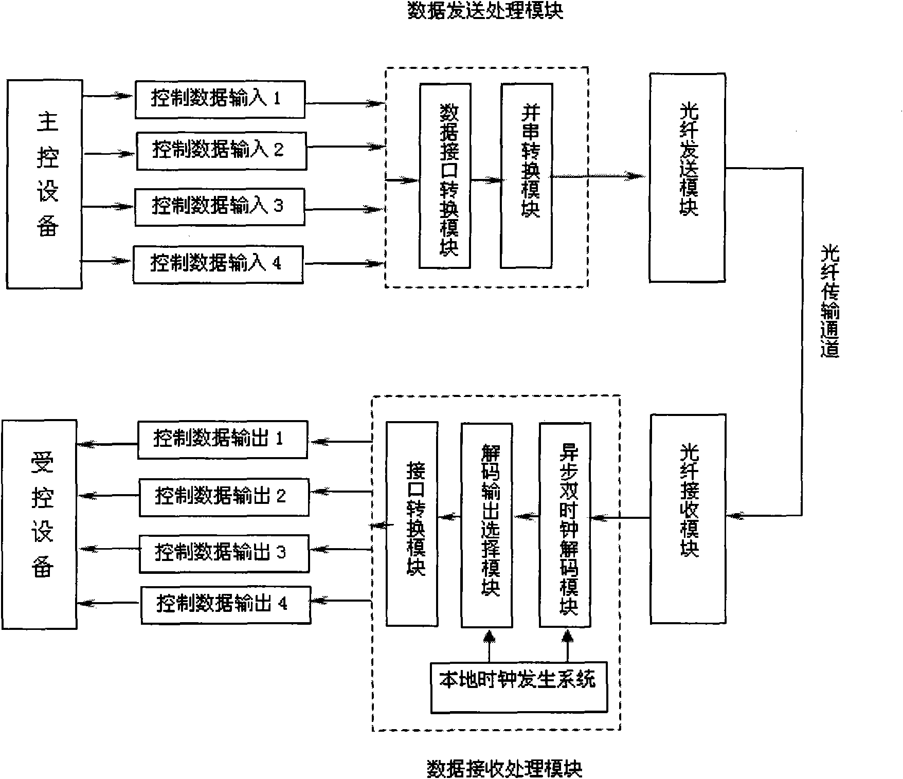
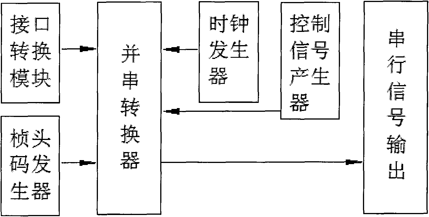
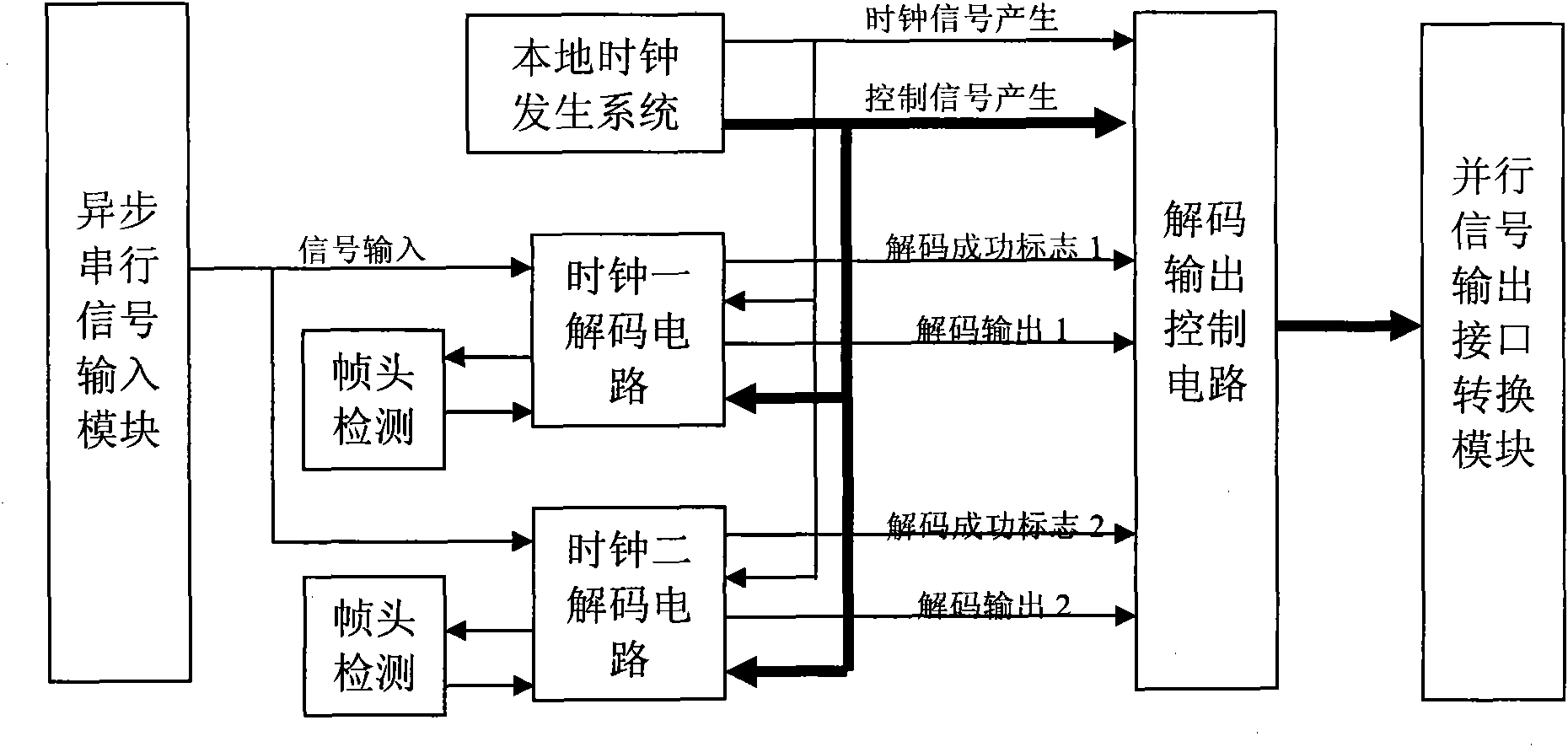
[0039] figure 1 It is a schematic diagram of the monitoring terminal data transmission system in the zero error transmission method of monitoring terminal data of the present invention; figure 2 It is a structural data block diagram of the data transmission processing module in the zero error code transmission method of monitoring terminal data of the present invention; image 3 It is a structural data block diagram of the data receiving and processing module in the zero-error transmission method of monitoring terminal data of the present invention; Figure 4 It is a working flow chart of zero bit error rate asynchronous serial decoding in the zero bit error transmission method of monitoring terminal data in the present invention.

[0040] Such as figure 1 As shown, the monitoring terminal control data transmission system in the present invention includes: a data t...


PUM


Abstract

The invention discloses a zero error transmission method for monitoring terminal data, wherein a clock generating system provides a double-clock decoding circuit and a clock system which enables a decoding output selection module to work. A clock for double-clock decoding respectively delays the time for a main clock at 0 degree and 180 degrees; a clock provided to the decoding output selection module delays the time for the main clock at 270 degrees; the control data is temporarily stored in two data registers after frame header and calibration inspection are completed and a decoding state marking bit is set; and the decoding output selection module selects correct decoding output data to an interface converting module according to the decoding output of an asynchronous double-clock decoding module and the decoding state marking bit. Because the double-decoding circuit is adopted to run at the same time, the system has no problem of error code during the overturning of the decoding clock, thereby the real-time decoding and no-error-code decoding can be effectively realized by the system.

Description

technical field [0001] The present invention relates to the technical field of monitoring terminals, in particular to a monitoring terminal data that adopts an asynchronous dual-clock decoding module and simultaneously utilizes a local clock and a local clock delayed by 180 degrees to decode data, thereby effectively reducing code errors generated when clocks are reversed Zero error transmission method. Background technique [0002] At present, with the development of the monitoring industry, the current monitoring is not just simple system construction such as video transmission and PTZ control of the front-end monitoring terminal, but the entire safe city system that includes applications such as intelligent transportation and public security networking. Point-to-point optical fiber transmission equipment with long-distance transmission capabilities has become an important part of the monitoring system. At this time, the control data that needs to be transmitted includes n...

Claims


Application Information

Patent Timeline
Patent Type & Authority Applications(China)
IPC IPC(8): H04N7/18H04N7/22H04N7/64H04N7/30H04N7/26H04N19/89
Inventor 戴林薛超
Owner TIANJIN TIANDY DIGITAL TECH
Why Eureka
Eureka Blog
Learn More