
System and method for transmitting data between service gateway and relay terminals

A service gateway and data transmission technology, applied in transmission systems, radio transmission systems, wireless network protocols, etc., can solve problems such as L2Relay did not give specific solutions

Inactive Publication Date: 2011-06-15
深圳市恒程汇文化科技有限公司
View PDF3 Cites 51 Cited by
  • Summary
  • Abstract
  • Description
  • Claims
  • Application Information

AI Technical Summary

Problems solved by technology

However, the existing technology does not give a specific solution for how to introduce L2Relay

Method used


Image

  • System and method for transmitting data between service gateway and relay terminals
  • System and method for transmitting data between service gateway and relay terminals
  • System and method for transmitting data between service gateway and relay terminals

Examples


Embodiment 1

[0115] The method for the Relay UE to receive user plane data from the s-GW is as follows Figure 5 shown, including the following steps:

[0116] Step 501: Establish an E-RAB connection between the Relay UE and the s-GW.

[0117] Including establishing a GTP-U tunnel (S1 bearer) between the s-GW and the Donor eNB, and establishing a data radio bearer (DRB, data radio bearer) connection between the Donor eNB and the Relay bound to the GTP-U tunnel . The identifier of the GTP-U tunnel is the downlink tunnel endpoint identifier (DL TEID, downlink Tunnel Endpoint Identifier), and the identifier of the DRB connection is the radio bearer identifier (RB Identity). The two are bound at the Donor eNB, that is, at the Donor eNB Establish the corresponding relationship between the identifier of the GTP-U tunnel and the identifier of the DRB.

[0118] One logical channel may correspond to one E-RAB connection, or multiple logical channels may correspond to one E-RAB connection.

[0119...

Embodiment 2

[0131] The method for Relay UE to send user plane data to s-GW is as follows: Image 6 shown, including the following steps:

[0132] Step 601: Establish an E-RAB connection between the Relay UE and the s-GW.

[0133] It includes establishing a GTP-U tunnel (S1 bearer) between the s-GW and the Donor eNB, and establishing a DRB connection between the Donor eNB and the Relay bound to the GTP-U tunnel. The identifier of the GTP-U tunnel is DL TEID, and the identifier of the DRB connection is RB Identity. The two are bound at the Donor eNB, that is, the corresponding relationship between the identifier of the GTP-U tunnel and the identifier of the DRB is established at the Donor eNB. .

[0134] Step 602: The uplink data sent by the Relay UE is received by the RN.

[0135] The application layer of the Relay UE submits the IP data packet to the PDCP layer. After the IP data packet is compressed and encrypted by the header of the PDCP entity, it forms a PDCP PDU and submits it to ...


PUM


Abstract

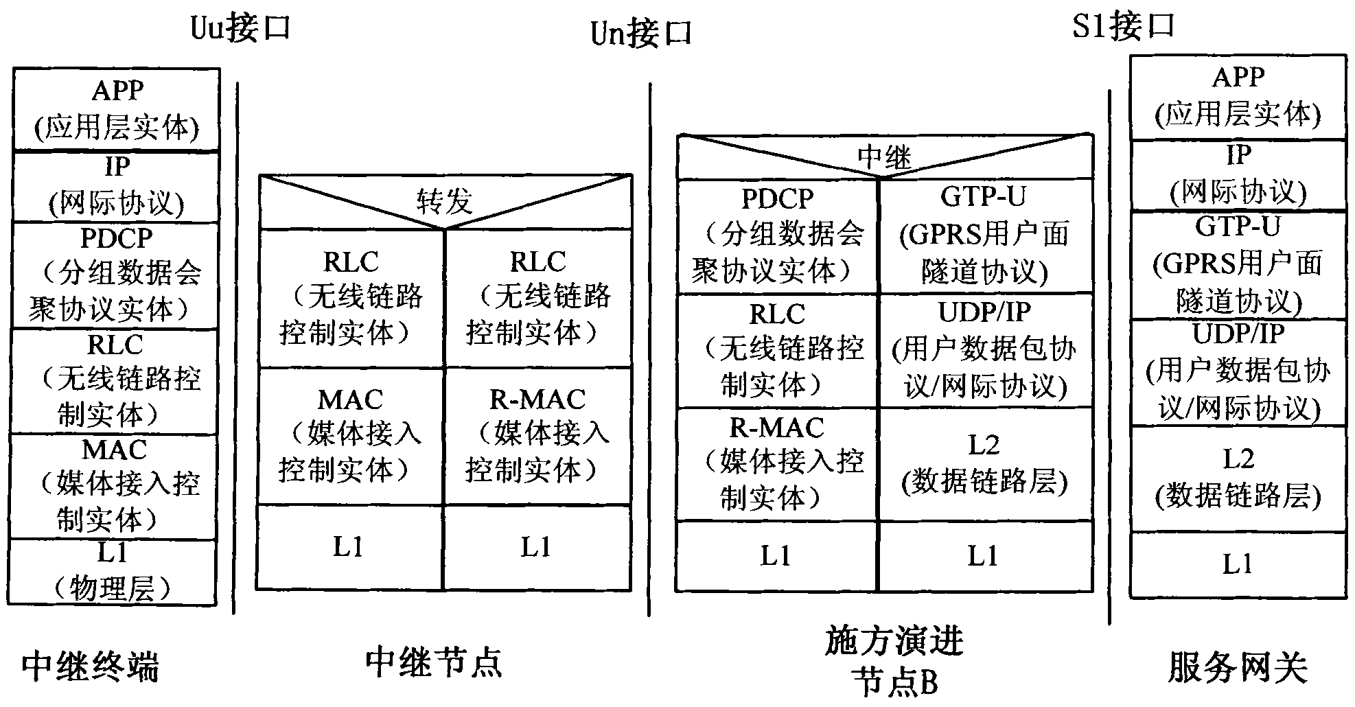
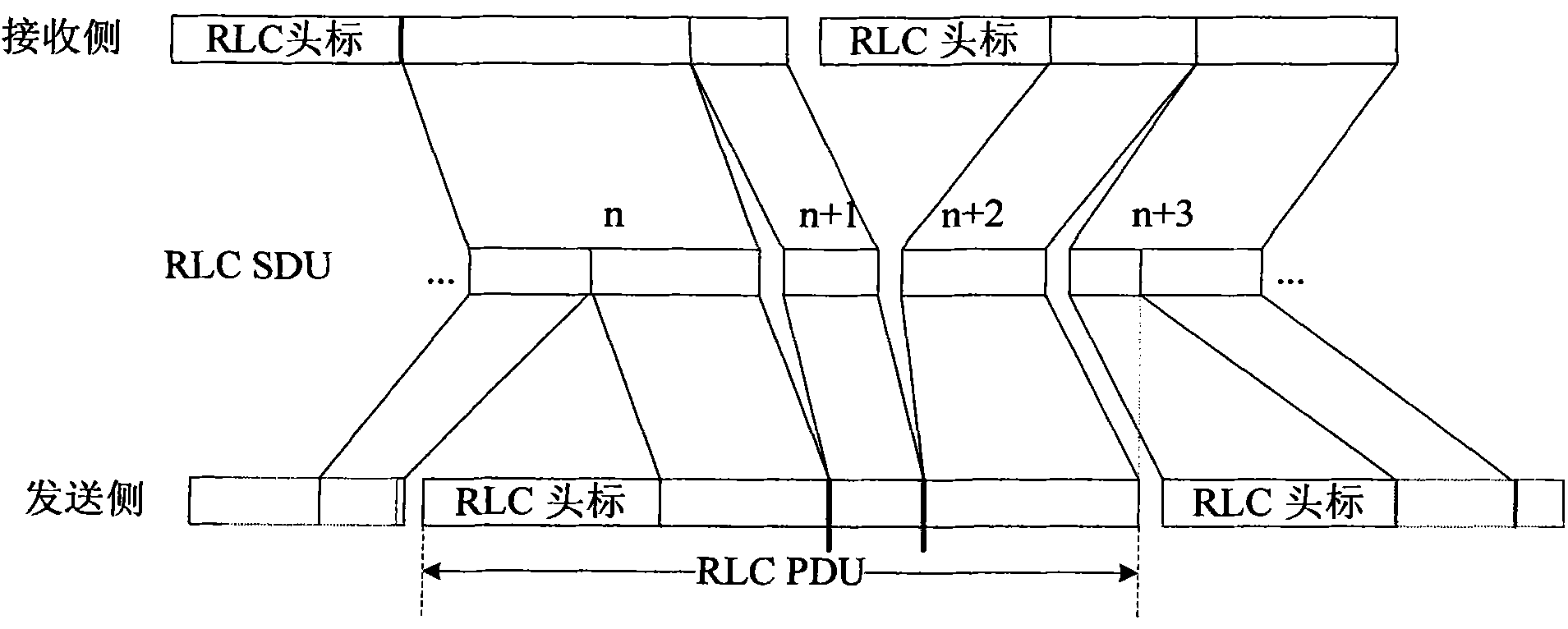
The invention provides a system and method for transmitting data between a service gateway and relay terminals. The method comprises the steps of: establishing evolution global terrestrial radio access bearer connection between the relay terminals and the service gateway; forming extracted packet data convergence protocol service data units (PDCP SDUs) into packet data convergence protocol protocol data units (PDCP PDUs) and multiplexing the PDCP PDUs to form radio link control protocol data units (RLC PDUs) after an evolution node B of an application side receives data sent by the service gateway; multiplexing the RLC PDU of each relay terminal to form a relay medium access control protocol data unit (R-MAC PDU) and then sending the R-MAC PDU to a relay node; extracting each RLC PDU from the R-MAC PDU by the relay node; and multiplexing all the RLC PDUs of the same relay terminal to form a media access control protocol data unit (MAC PDU) and then sending the MAC PDU to the corresponding relay terminal. By adopting the invention, the aims of introducing the relay node, reducing the cost and improving the efficiency are realized.

Description

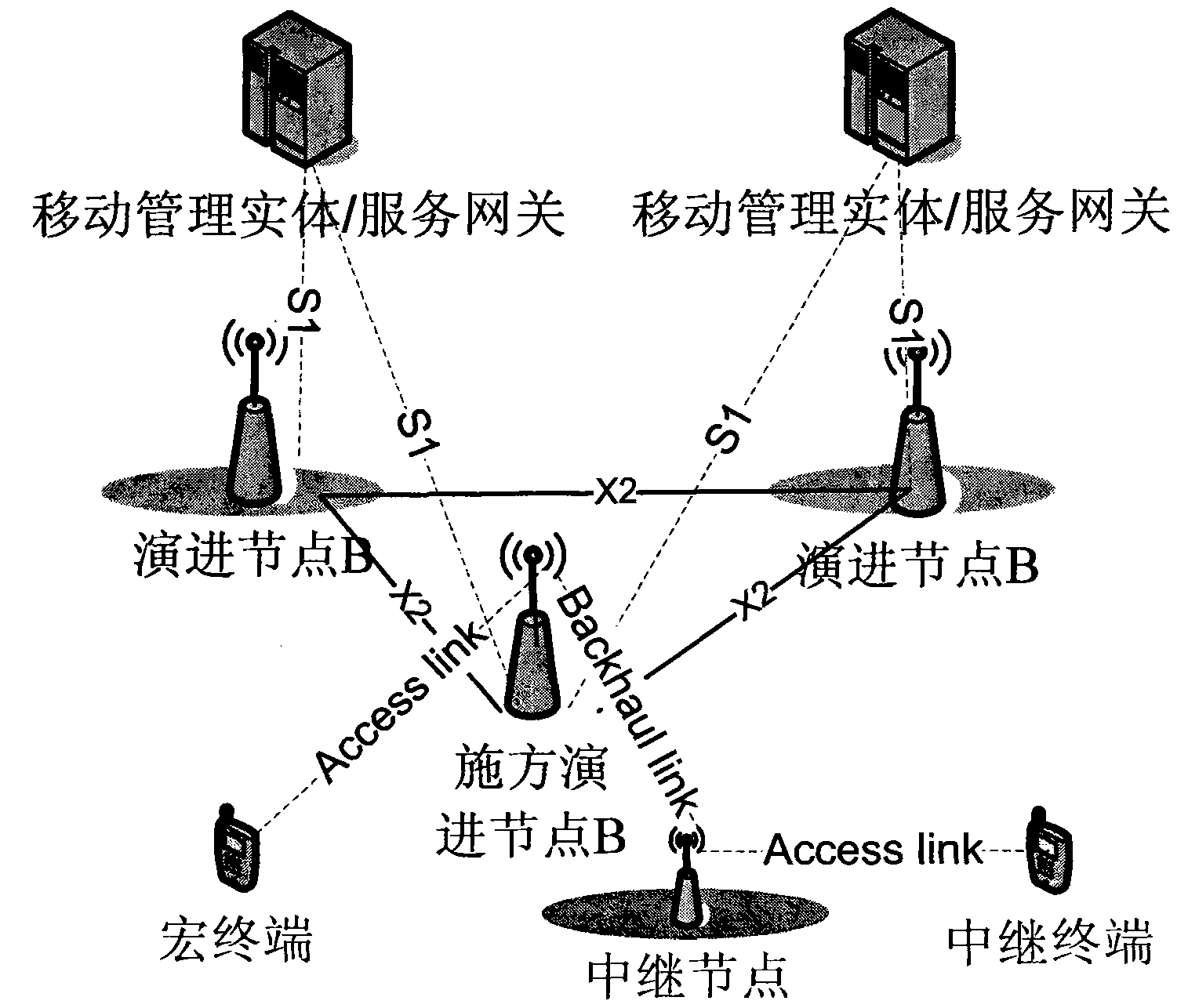
technical field [0001] The present invention relates to a long term evolution system (LTE, long term evolution) in the field of wireless communication, in particular to a system and method for transmitting data between a serving gateway and a relay terminal in an advanced long term evolution system (LTE-A, LTE Advanced). Background technique [0002] The 3rd Generation Partnership Project (3GPP, The 3rd Generation Partnership Project) determines that the LTE architecture is a flat evolved UMTST Terrestrial Radio Access Network (e-UTRAN, evolved UMTST Terrestrial Radio Access Network) structure. like figure 1 As shown, the user plane is mainly composed of two parts: an evolved node B (eNB, evolved Node B) and a serving gateway (s-GW, serving-gateway). The eNB is connected to the s-GW through the base station-gateway interface S1, the eNBs are connected through the inter-base station interface X2, and the user equipment (UE, User Equitmemt) is connected to the eNB through the...

Claims


Application Information

Patent Timeline
Patent Type & Authority Applications(China)
IPC IPC(8): H04W28/06H04W72/12H04W80/04H04W92/10
CPCH04B7/155
Inventor 王坚
Owner 深圳市恒程汇文化科技有限公司
Learn More