Dual clutch

A dual-clutch, clutch housing technology, applied in clutches, fluid-driven clutches, mechanical-driven clutches, etc., can solve problems such as hysteresis

Inactive Publication Date: 2011-06-15
SCHAEFFLER TECH AG & CO KG
View PDF8 Cites 24 Cited by
  • Summary
  • Abstract
  • Description
  • Claims
  • Application Information

AI Technical Summary

Problems solved by technology

In addition, the configuration of the axial stroke relative to the actual stroke of the pressure plate is declining or showing a lag

Method used


Image

  • Dual clutch
  • Dual clutch
  • Dual clutch

Examples


Embodiment Construction

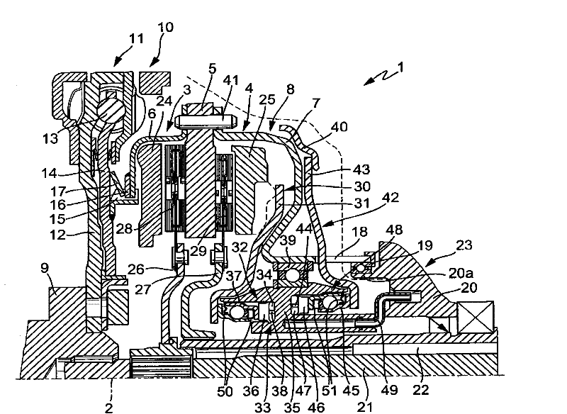
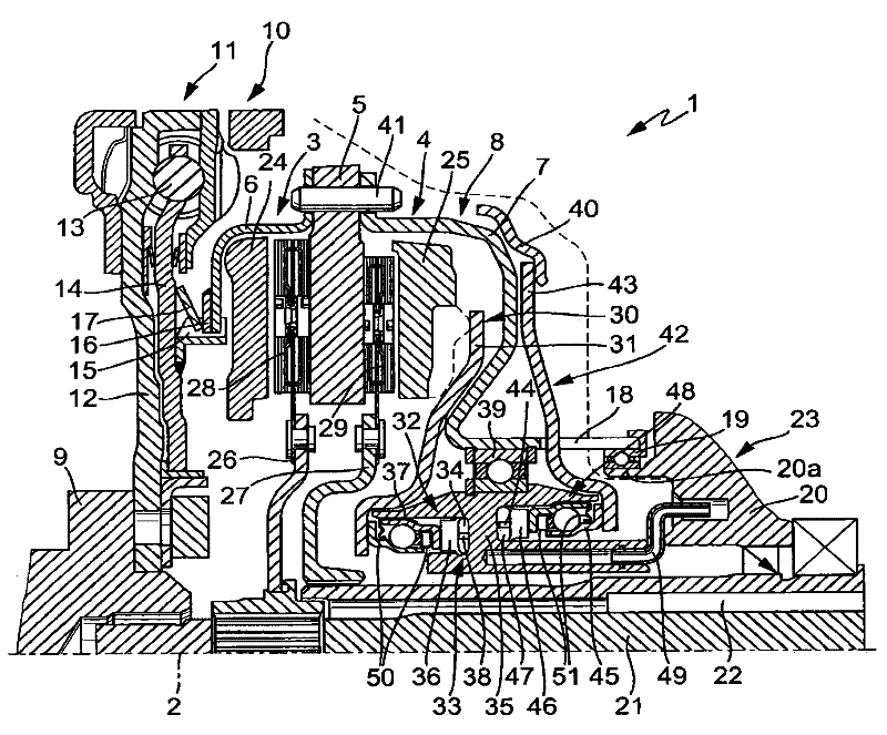
[0030] figure 1 A dual clutch 1 is shown in partial section above its axis of rotation 2 . The dual clutch 1 comprises two friction clutches 3 , 4 which have a common central pressure plate 5 which is fixedly connected to the housing parts 6 , 7 of the clutch housing 8 . The clutch housing 8 is driven by a crankshaft 9 of a not shown internal combustion engine. To this end, in the exemplary embodiment shown, a torsional vibration damper 10 —here in the form of a dual-mass flywheel 11 —is connected with its input part 12 to the crankshaft 9 . The output part 14, which can be twisted to a limited extent relative to the input part 2 against the action of the energy store 13, has a forwardly protruding tooth profile 15 in which a complementary tooth profile 16, such as that of the housing part 6 shown, engages. An internal tooth section. In the exemplary embodiment shown here, the dual clutch 1 is held relative to the crankshaft 9 and relative to the torsional vibration damper ...


PUM


Abstract

The invention relates to a dual clutch (1) having two friction clutches (3,4), having a central pressure-exerting plate (5) and having two pressure plates (24,25) which are axially movable relative to said pressure-exerting plate (5) with the interposition of the friction linings (28,29) of two clutch disks (26,27), which mesh with in each case one gearbox input shaft (21,22), of actuating devices (32,32a). Here, the pressure plates (24,25) are advantageously acted on by transmission elements (30,42,69,70) by the actuating devices (32,32a) directly without a lever action. Furthermore, for the cooling and lubrication of the actuating devices (32,32a) and the transmission elements (30,42,69,70), an annular chamber (58) can be formed which has an increased fluid volume.

Description

technical field [0001] The invention relates to a double clutch with two friction clutches driven by a drive unit, which are provided with a common clutch housing, a pressure plate with two pressure surfaces fixedly connected to the housing, and two respective Axially movable pressure plate towards a pressure bearing surface. Background technique [0002] Double clutches are known which have two friction clutches with a clutch housing and a central pressure plate fixedly connected to the housing. The pressure plate is moved axially by the actuating device in that a disk spring or a lever part is axially loaded radially inwardly with a predetermined clutch travel. In this case, depending on the configuration of the associated friction clutch as a friction clutch that is forcibly pressed together, that is, forcibly closed, or forcibly pressed, that is, forcibly opened, these lever parts are supported on the clutch housing as single-armed or double-armed levers. And constitut...

Claims


Application Information

Patent Timeline
Patent Type & Authority Applications(China)
IPC IPC(8): F16D21/06F16D25/08F16C33/76
CPCF16D21/06Y02T10/76F16D2300/021F16D25/083F16D2021/0669F16D25/10F16C2361/43F16C37/007F16C19/54F16D2021/0607F16D25/08Y02T10/60
Inventor O·诺尔
Owner SCHAEFFLER TECH AG & CO KG
Why Eureka
Try Eureka