Supercharge Your Innovation With Domain-Expert AI Agents!

A controlled overlap driver circuit

A technology for driving circuits and control circuits, applied in electrical components, regulating electrical variables, control/regulating systems, etc., to achieve the effect of eliminating voltage spikes

Active Publication Date: 2011-06-15
亚德诺半导体股份有限公司
View PDF5 Cites 7 Cited by
  • Summary
  • Abstract
  • Description
  • Claims
  • Application Information

AI Technical Summary

Problems solved by technology

In this typical application, a large amount of distortion can be introduced into the analog signal voltage across the load by the voltage spike caused by the interruption of the current path during the off-time

Method used


Image

  • A controlled overlap driver circuit
  • A controlled overlap driver circuit
  • A controlled overlap driver circuit

Examples


Embodiment Construction

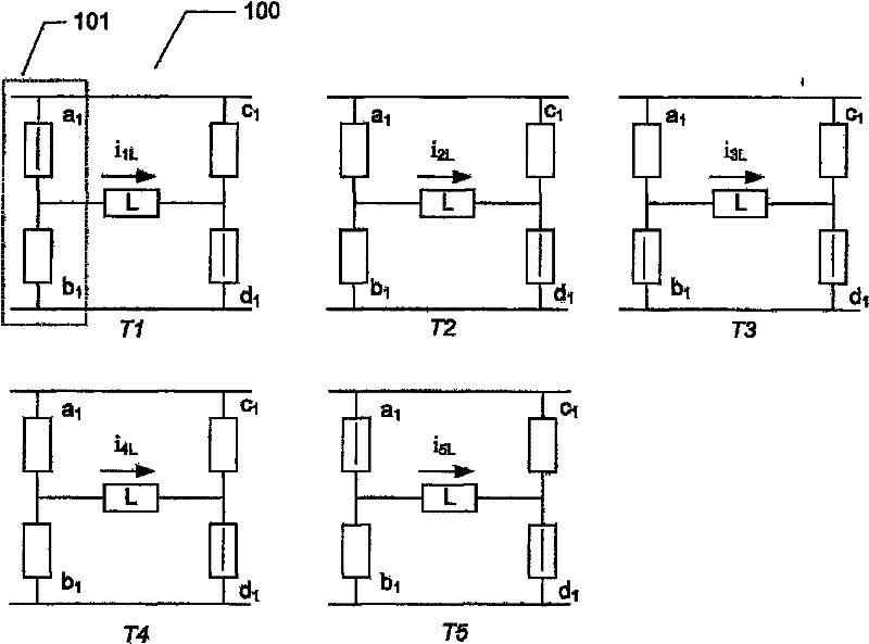
[0057] figure 1 It schematically shows each of the two branches a1 and b1 of the left half of the H-bridge 101 of the prior art H-bridge driver 100 according to the prior-art timing scheme of various control signals applied to the control input of the semiconductor switch. The timing of semiconductor switches. The timing scheme is set to deliberately establish an intermediate dead time or cut-off time between the output state transitions of each driver of the H-bridge as shown for the left half of the H-bridge 101 related to the states T2 and T4.

[0058] figure 2 Shown in figure 1 The electrical model of the left half of the H-bridge 101 of the prior art H-bridge 100 is schematically illustrated in. Will drive output V OUTL Connected to load L, the load includes a series pass inductor L L The simulated effective inductive components and through R L The simulated resistance component. In the following implementations of SWa1 and SWb1 based on CMOS transistors, the V OUTL Ther...


PUM


Abstract

The present invention relates to a driver circuit wherein upper and lower legs of a first driver comprise first and second sets of parellelly coupled semiconductor switches, respectively. A control circuit is configured to generate respective control signals for the first and second sets of parellelly coupled semiconductor switches to create a current path through the upper and lower legs during an overlap time period between state transitions of a driver output.

Description

Technical field [0001] The present invention relates to a driving circuit, wherein the upper branch and the lower branch of a first driver respectively include a first group and a second group of parallel semiconductor switches. The control circuit is configured to generate various control signals for the first and second groups of parallel semiconductor switches to establish a current path through the upper branch and the lower branch during the overlap period between the state transitions of the drive output. Specifically, the present driving circuit is suitable for applications in order to drive an electric load with actual inductance components. Background technique [0002] A drive circuit for providing drive voltage and current to an electric load like a speaker or a motor is known in the art. These drive circuits are connected to a pair of power supply voltages to transmit a signal to an electric load or drive power in the form of, for example, an audio signal. The H-bri...

Claims


Application Information

Patent Timeline
Patent Type & Authority Applications(China)
IPC IPC(8): H02M3/158H02M3/156
CPCH02M3/158H02M3/156
Inventor 穆罕默德·沙扬亨里克·汤姆森
Owner 亚德诺半导体股份有限公司
Features
  • R&D
  • Intellectual Property
  • Life Sciences
  • Materials
  • Tech Scout
  • Unparalleled Data Quality
  • Higher Quality Content
  • 60% Fewer Hallucinations
Learn More