
Optical glass strip rolling and moulding device

A technology of optical glass and roll forming, which is applied in glass forming, glass rolling, glass manufacturing equipment, etc. It can solve problems such as inconsistent fillet size, lower utilization rate of glass sheet material, and inconsistent cooling speed of the upper and lower sides.

Active Publication Date: 2014-04-02
HUBEI NEW HUAGUANG NEW INFORMATION MATERIALS CO LTD
View PDF3 Cites 0 Cited by
  • Summary
  • Abstract
  • Description
  • Claims
  • Application Information

AI Technical Summary

Problems solved by technology

[0002] At present, the production of domestic optical glass sheets has been simply formed by open molds. The glass liquid is naturally cooled and formed in the mold. Due to thermal expansion and contraction and the effect of surface tension during molding, there is a certain amount of shrinkage at the upper and lower corners. As a result, there are large rounded corners after the glass sheet is cooled and solidified in the mold cavity, and the cooling speed of the upper and lower sides is inconsistent, and the size of the rounded corners formed is also inconsistent. The smaller the thickness, the larger the rounded corners, making the glass cross-section appear trapezoidal, Irregular shapes such as arcs reduce the material utilization rate of glass sheets, so it is imperative to design and manufacture a glass sheet forming equipment to improve this situation

Method used


Image

  • Optical glass strip rolling and moulding device
  • Optical glass strip rolling and moulding device
  • Optical glass strip rolling and moulding device

Examples


Embodiment Construction

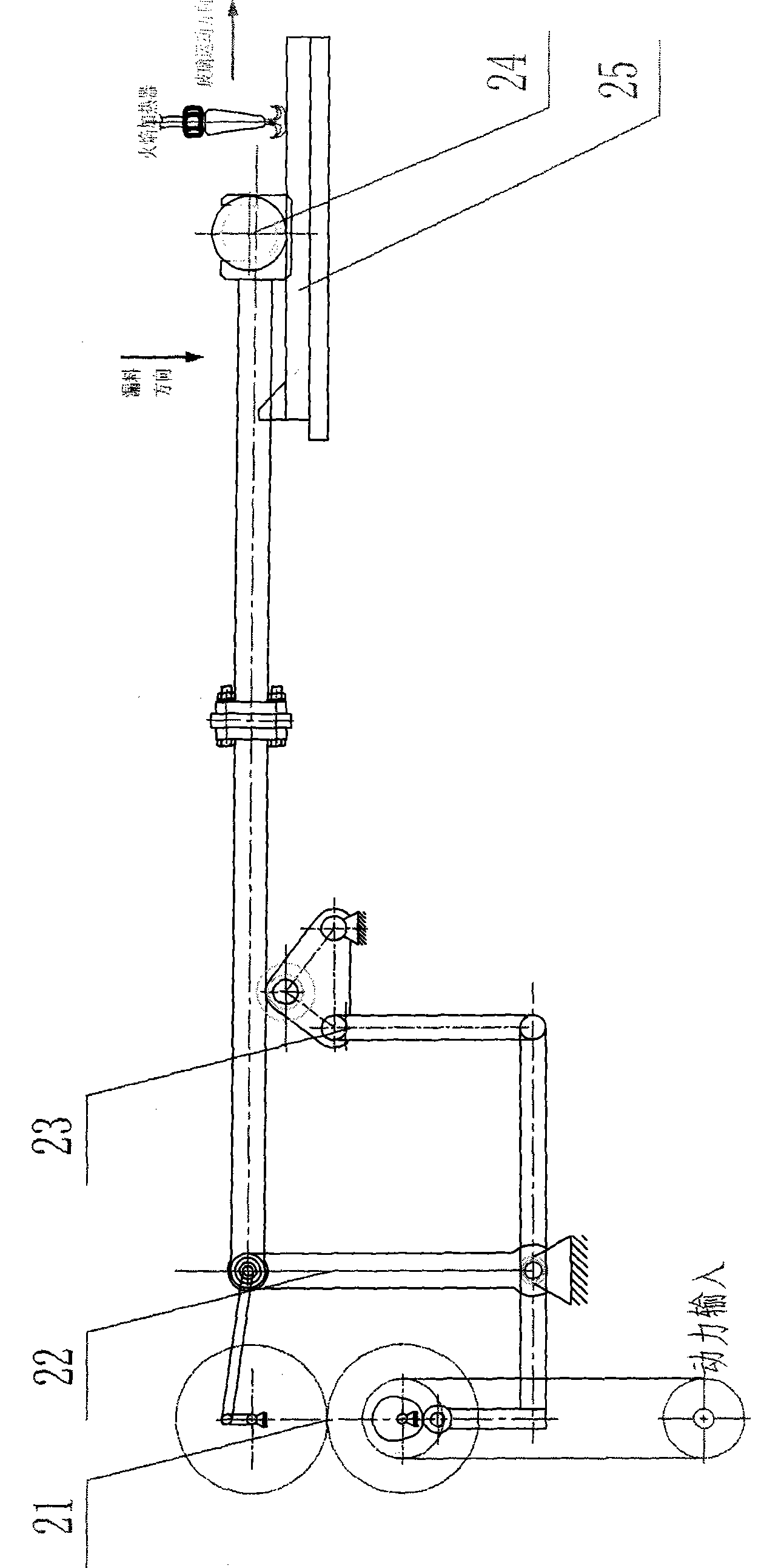
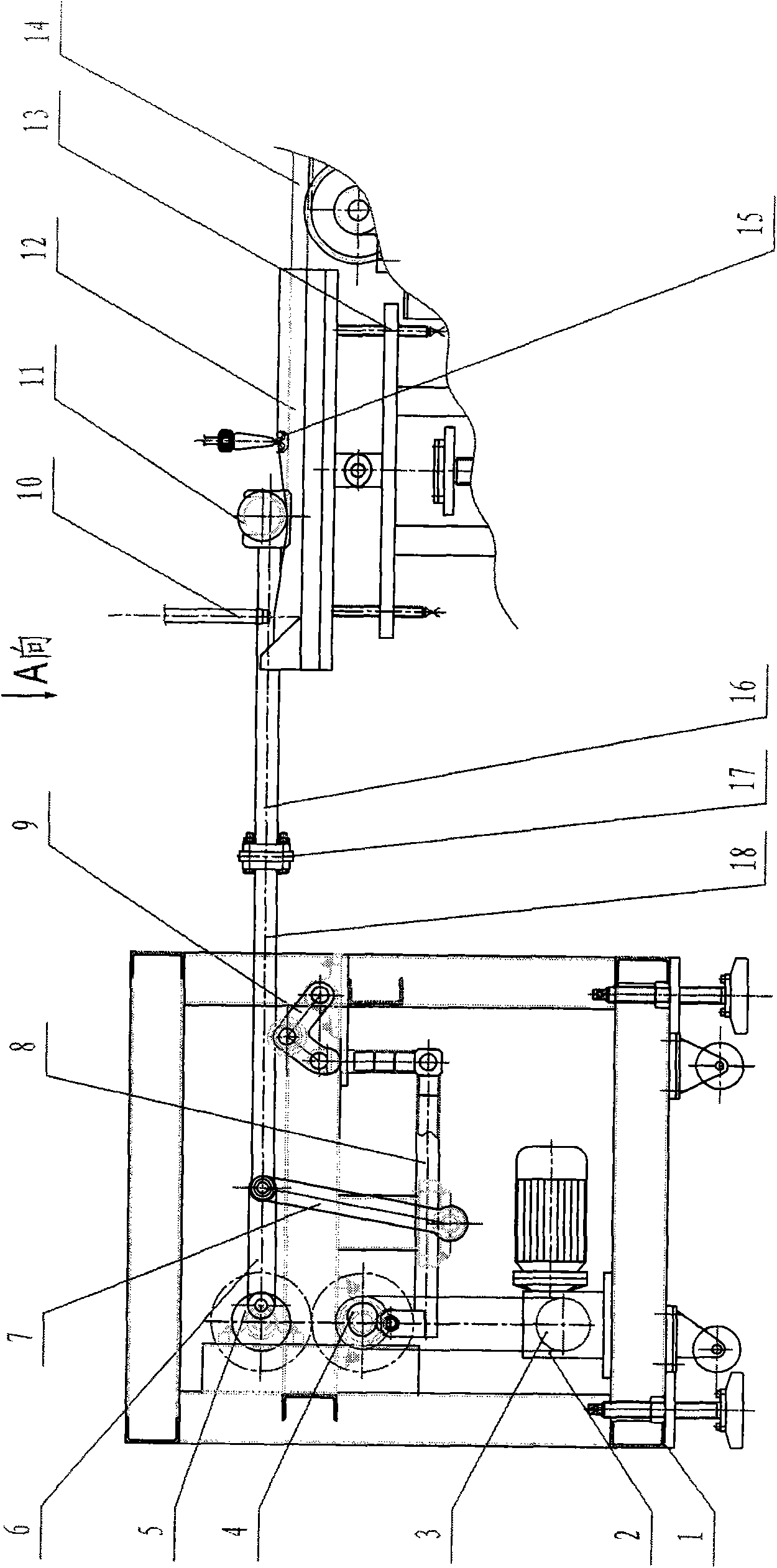
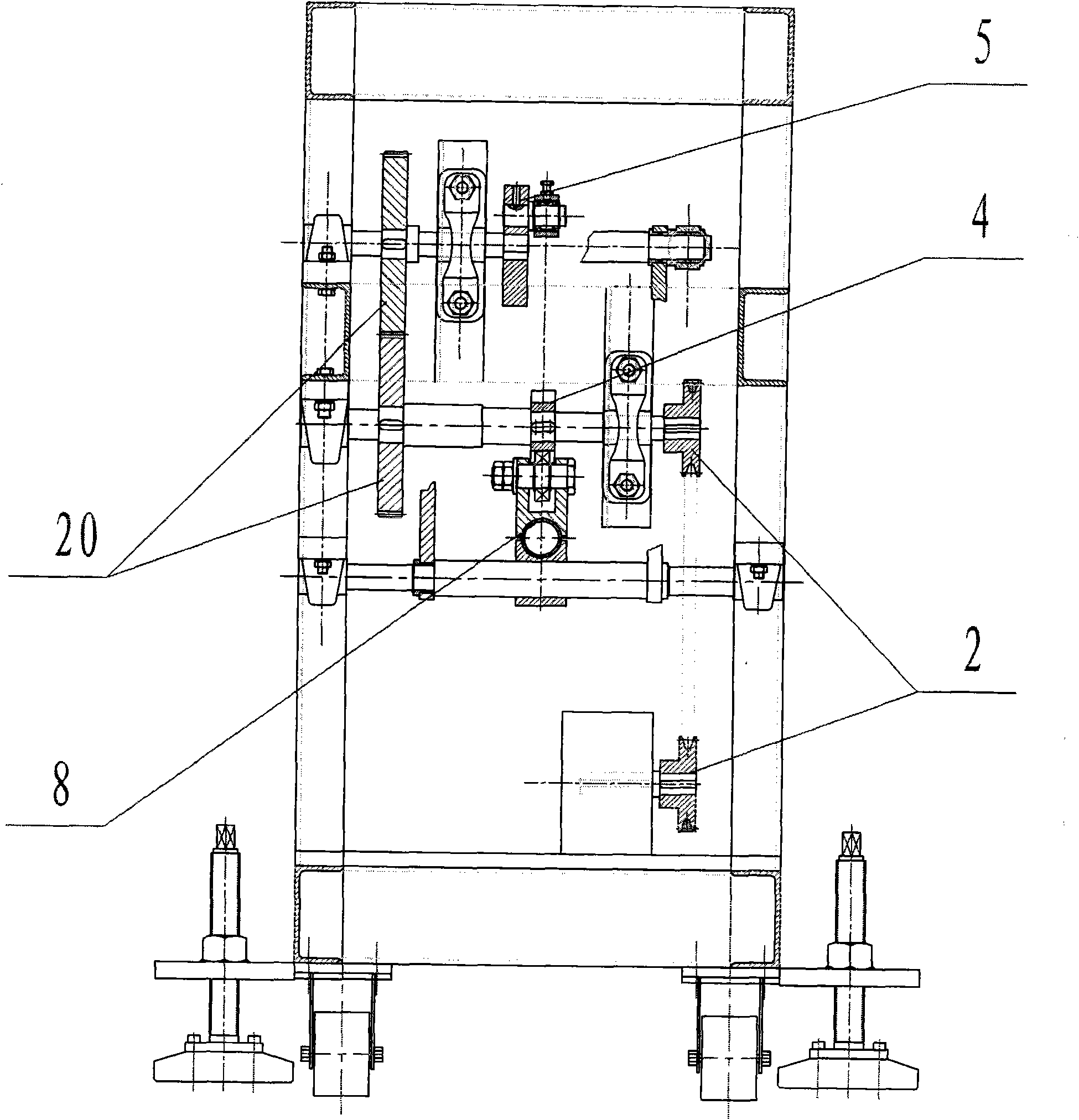
[0017] like figure 2 , 3 , shown in 4 and 5: the present invention is fixed on frame 1 and drive pulley 3 to drive a pair of cylindrical gears 20 that are completely identical in size and meshed up and down. The crank is installed coaxially with the upper cylindrical gear 20. The eccentric hole is connected with the moving end of the rocker 7 and the end of the support rod 18 through the connecting rod 6. The eccentricity (crank length) is half of the roller stroke, and the length of the rocker 7 is eccentric Eleven to twelve times the distance. The cam 4 is coaxially installed with the lower cylindrical gear 20. By pushing the small roller at one end of the linear lever 8 to move up and down, the triangular lever 9 is driven to lift (down) the support rod 18, and the support rod 18 falls into the top support roller of the triangular lever 9. In the groove of 19, the support rod 18 can move horizontally with the crank linkage mechanism when it moves up and down. The value ...


PUM


Abstract

The invention relates to an optical glass strip rolling and moulding device which belongs to the technical field of optical glass melting plate one-step thermal moulding devices. The invention mainly solves the problem of larger circular bead and thickness control existing in an open type die moulding. The optical glass strip rolling and moulding device is mainly characterized by comprising a gear synchronous drive system, a crank connecting rod motion system, a cam lever system, an optical glass moulding and rolling barrel, an optical glass moulding die and a power system, wherein the gear synchronous drive system comprises a pair of cylindrical gears with same size; the crank connecting rod motion system comprises an eccentric wheel, a connecting rod and a rocker; the cam lever system comprises a cam, a linear lever, a triangular lever and a support rod; and the optical glass moulding and rolling barrel comprises a door-shaped bracket, a roller and a roller cooling system. The invention has the characteristic of improving the appearance size moulding precision of an optical glass plate (especially a thin plate) and is the optical glass strip rolling and moulding device which is mainly used for carrying out one-step thermal moulding on the molten optical glass plate.

Description

technical field [0001] The invention belongs to the technical field of one-time thermoforming device for optical glass smelting sheets. In particular, it relates to a combination method of an open cavity mold and a mechanical one-way discontinuous roll pressing, and an optical glass strip roll forming device for one-time thermoforming of the smelted optical glass sheet. Background technique [0002] At present, the production of domestic optical glass sheets has been simply formed by open molds. The glass liquid is naturally cooled and formed in the mold. Due to thermal expansion and contraction and the effect of surface tension during molding, there is a certain amount of shrinkage at the upper and lower corners. As a result, there are large rounded corners after the glass sheet is cooled and solidified in the mold cavity, and the cooling speed of the upper and lower sides is inconsistent, and the size of the rounded corners formed is also inconsistent. The smaller the thic...

Claims


Application Information

Patent Timeline
Patent Type & Authority Patents(China)
IPC IPC(8): C03B13/01
Inventor 李兢何学华
Owner HUBEI NEW HUAGUANG NEW INFORMATION MATERIALS CO LTD
Learn More