Split joint-fork type cross universal joint

A cross shaft universal and cross shaft technology, applied in the direction of couplings, elastic couplings, mechanical equipment, etc., can solve the problems of high assembly consistency, difficult to overlap, aggravate mechanical wear, etc., to achieve simple assembly and easy adjustment. , the effect of high work quality

Inactive Publication Date: 2011-06-22
洪涛
View PDF7 Cites 2 Cited by
  • Summary
  • Abstract
  • Description
  • Claims
  • Application Information

AI Technical Summary

Problems solved by technology

However, the two improved universal joints still have the same disadvantages as ordinary cross-axis universal joints
That is to say, the operation and adjustment of the seat hole in the assembly of the cross shaft is too time-consuming, and it depends more on human subjective factors, tooling fixtures or subsequent detection factors. Even if there are high-precision parts, It is also not easy to ensure that the intersection of the cross axis coincides with the intersection of the axes of the two drive shafts required by the design, so that the axis of at least one drive shaft of the universal joint is not easy to coincide with its actual axis of rotation
Therefore, there is a possibility of reducing the working quality of the universal joint and aggravating its mechanical wear, and therefore it is difficult to adapt to high-speed transmission, and the elimination of this possibility depends more on the high quality and time-consuming assembly, which not only increases the cost but also reduces the cost. Easy to ensure high assembly consistency
In other words, high-precision parts production cannot ensure high-quality universal joints, which must rely on high-quality assembly
In addition, the quality of the adjustment to eliminate the gap in use, such as after wear, is less likely to be guaranteed

Method used


Image

  • Split joint-fork type cross universal joint
  • Split joint-fork type cross universal joint
  • Split joint-fork type cross universal joint

Examples


Embodiment 1

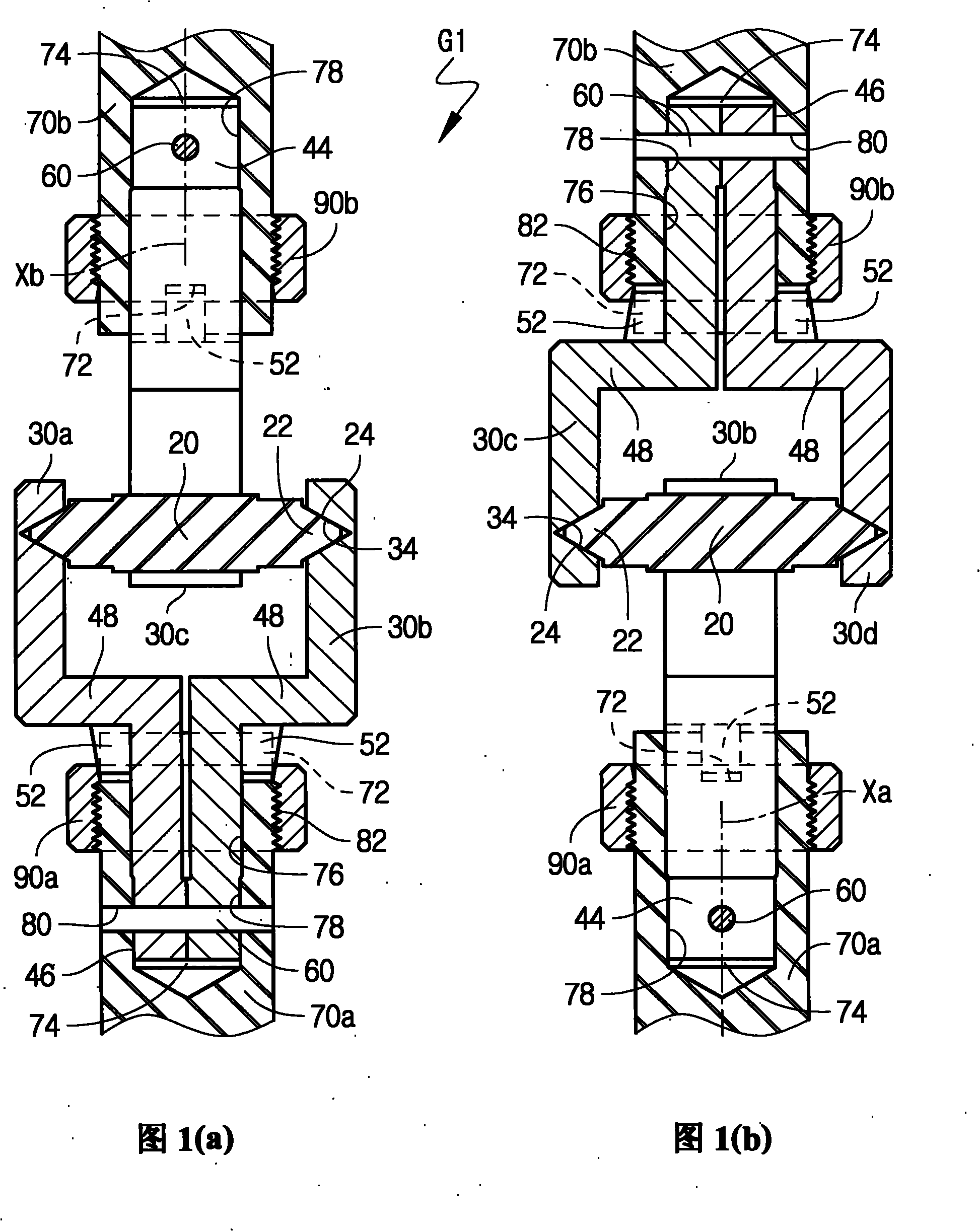
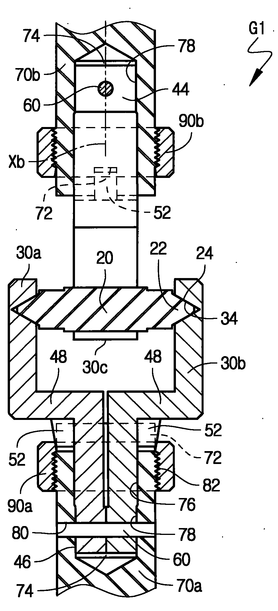
[0019] Example 1: Split yoke cross shaft universal joint G1 with conical joint surface

[0020] Referring to Figures 1-2, the universal joint G1 includes a cross shaft and a universal joint fork as in the prior art. Wherein, the universal joint yoke is a combined joint yoke comprising two radially butted half joint yokes 30 . The cross shaft 20 includes four shaft heads 22 provided with outer conical rotary working surfaces 24 . The four rotary working surfaces 24 are correspondingly accommodated in the cross shaft seat holes 32 of the inner conical rotary working surfaces 34 with complementary structures provided on the four half-joint forks 30a, 30b, 30c and 30d. Obviously, in addition to the conical surface, the revolving working surfaces 24 and 34 can also be other arbitrary shapes of revolving curved surfaces, as long as their gyration radius generally has the characteristics that one end is large and the other end is small along the axial direction, and it is considered...

Embodiment 2

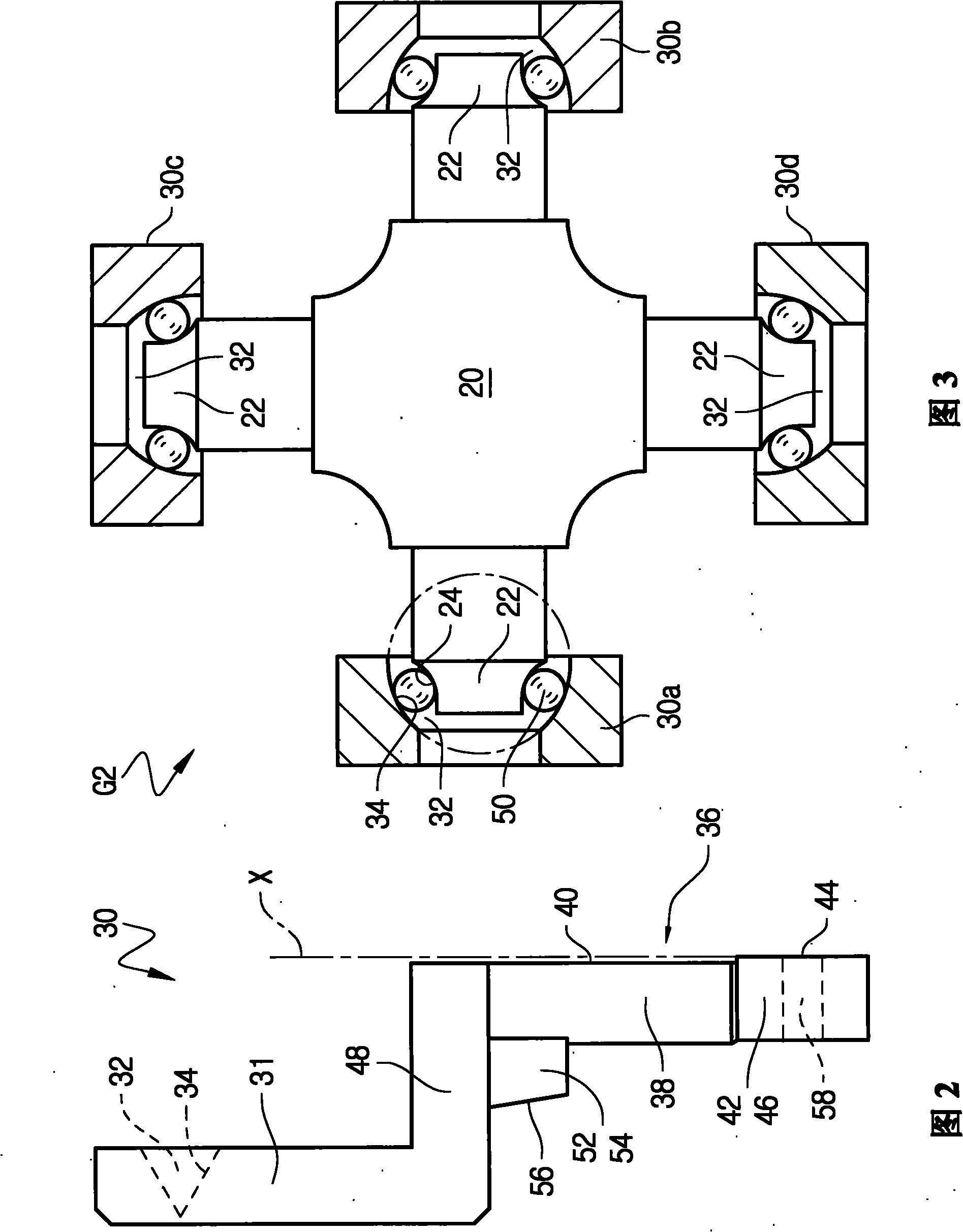
[0032] Embodiment 2: Split fork type cross shaft universal joint G2 with ball bearings

[0033] like image 3 As shown, the universal joint G2 is an improvement on the universal joint G1, the difference is only that in order to reduce the frictional resistance and radial separation force in the work, the rotating working surface 34 of the cross shaft seat hole is changed from the inner conical surface to Inner arc-shaped surface, the outer conical rotary working surface 24 on the cross shaft 20 is converted from an outer conical surface to an outer arc-shaped surface, and there is an interval between the two rotary surfaces to best fill the entire circumferential ring A set of balls 50 in space.

[0034] Apparently, a group of balls 50 in the universal joint G2 is equivalent to a ball bearing without inner and outer rings. Such arrangement is beneficial to simplify its structure, manufacturing and assembly process, and correspondingly have higher transmission accuracy. Of co...


PUM


Abstract

The invention relates to a split joint-fork type cross universal joint which is characterized in that the universal joint fork is a composite member comprising two half joint forks, and a whole rotation axis which is formed by the radial butt joint of the axial tail sections of the two half joint forks is inserted in an axial hole which is arranged at one end of a joint-fork shaft sleeve by utilizing a way of interference connection and is axially and relatively fixed by a stop bolt which is connected in a corresponding radial hole of the two half joint forks by utilizing the way of the interference connection. By means of end face tabling with the joint-fork shaft sleeve, the two half joint forks are located in circumference direction and the carrying capacity is increased; by means of the symmetrical radial compression of a regulating nut arranged on the outer circumference face to the outer conical surface of the end face tooth, the gap between the half joint fork and a cross shaft as well as the compaction degree can be regulated; therefore, the high quality of assembling can be obtained with cordwood simple splicing operation and rapid regulation; the influence of nonobjective factors in the assembling process on the working quality of the universal joint can be removed in the maximal degree; and finally the universal joint capable of doing high-precision universal drive can be rapidly and reliably obtained.

Description

technical field [0001] The invention relates to a shaft coupling / universal joint for intersecting shafts in the field of mechanical transmission, in particular but not only to a cross shaft type universal joint capable of precision transmission. Background technique [0002] Because the ordinary cross-axis universal joints in the prior art more or less have rotation clearance / idle travel, they are generally difficult to meet the high-precision transmission requirements in high-precision work fields such as ultra-precision machining. Documents CN100385132C and CN100462578C respectively disclose two types of improved cross-axis universal joints with high-precision transmission capability. But the two improved universal joints still have the same disadvantages as the common cross axis universal joints. That is to say, the operation and adjustment of the seat hole in the assembly of the cross shaft is too time-consuming, and it depends more on human subjective factors, tooling ...

Claims


Application Information

Patent Timeline
Patent Type & Authority Applications(China)
IPC IPC(8): F16D3/27
Inventor 洪涛
Owner 洪涛
Why Eureka
Try Eureka