Vehicle cutting energy absorption device for rail locomotive

An energy-absorbing device, a technology for rail locomotives, which are applied in railway vehicle wheel guards/buffers, transportation and packaging, railway car body components, etc., can solve problems such as easy failure, large volume, limited energy absorption and energy absorption travel , to achieve the effect of good energy absorption, small volume and reasonable structure

Inactive Publication Date: 2011-06-29
CENT SOUTH UNIV
View PDF5 Cites 33 Cited by
  • Summary
  • Abstract
  • Description
  • Claims
  • Application Information

AI Technical Summary

Problems solved by technology

Energy absorbing protection devices used in other fields, such as hydraulic type and spring type, have limitations such as large volume, easy failure during work, limited energy absorption and energy absorption stroke, and have not been adopted by rail rolling stock

Method used


Image

  • Vehicle cutting energy absorption device for rail locomotive
  • Vehicle cutting energy absorption device for rail locomotive

Examples


Embodiment 1

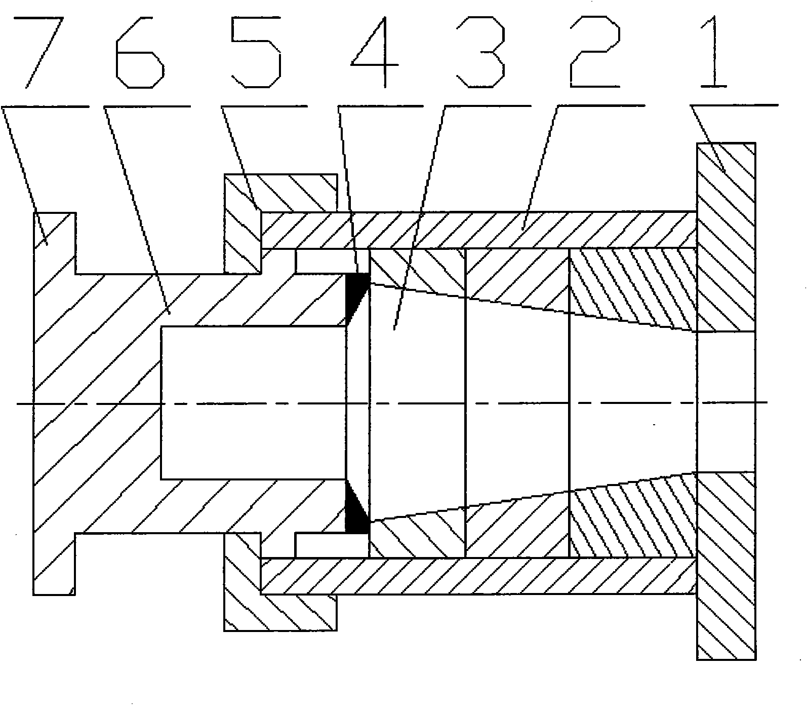
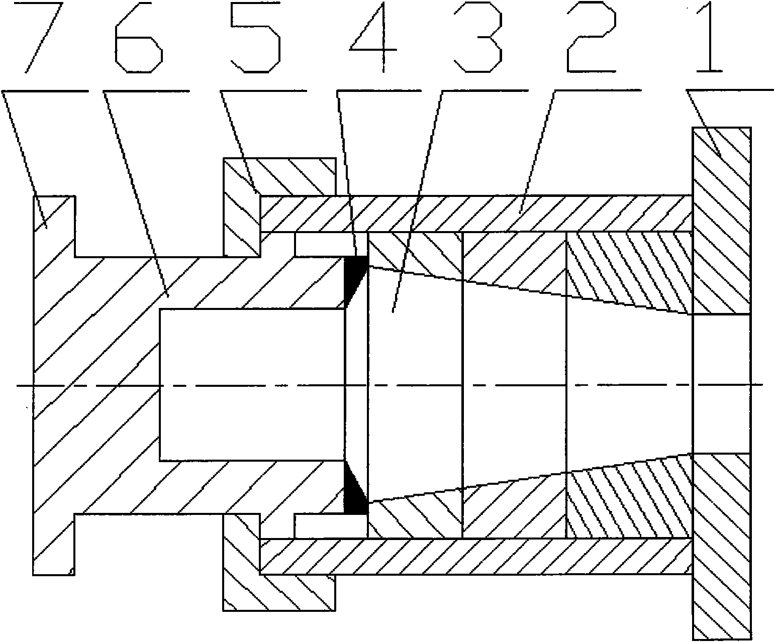
[0025] Referring to the accompanying drawings: the shell 2 is a hollow cylindrical structure, and its two ends are respectively connected to the base 1 and the end cover 5, the base 1 is connected to the locomotive vehicle, and the workpiece 3 is installed in it; normally, the blade of the tool 4 is connected to the workpiece to be cut. 3 contacts, the tool 4 is provided with a tool bar 6, and the end of the bar body of the tool bar 6 exposed to the shell 2 is installed with an impact plate 7; when the tool bar 6 encounters an external impact source, the blade of the tool 4 is inserted into the workpiece 3 to perform cutting and work absorption can. In this embodiment, the blades of the cutter 4 are divided into two groups, the blades of the same group are arranged on the same plane and the same circumference, and the blades of the other group are arranged on another same plane and the same circumference. The cut piece 3 has a variable cross-section and is made of three materi...

Embodiment 2

[0027] It is basically the same as the embodiment, except that the blade of the cutter 4 is in a spiral shape. Under the force of the impact source, the cutter 4 advances in a spiral manner, which obviously increases the path length of the cutter and reduces the volume of the device.

[0028] Embodiments of other combinations will not be described in detail.

[0029] When the cutting edge of the tool 4 is inserted into the workpiece 3 to cut off a set cutting layer, two processes of energy conversion and deceleration and buffering are included.

[0030] The process of energy conversion is to convert the energy of the impact source into heat energy, internal energy of cutting work or other energy through cutting work, so as to achieve the purpose of consuming the energy of the impact source.

[0031] The process of deceleration and buffering, that is, by setting the parameters of the tool 4 and the workpiece 3, the travel speed of the tool 4 is set to change from fast to slow,...


PUM


Abstract

The invention discloses a vehicle cutting energy absorption device for a rail locomotive. The device comprises a base (1), a shell (2), a cut piece (3), a cutter (4), an end cover (5) and a cutter bar (6); the shell (2) is of a hollow cylinder structure, two ends of the shell (2) are connected with the base (1) and the end cover (5) respectively, and the cut piece (3) is arranged in the shell (2); the cutting edge of the cutter (4) is contacted with the cut piece (3), the cutter (4) is provided with the cutter bar (6), and a part of bar body of the cutter bar (6) is exposed out of the shell (2); and when the cutter bar (6) encounters an external impact source, the cutting edge of the cutter (4) is inserted into the cut piece (3) to cut the set cutting layer. When the cutter (4) has one group of blades, the blades are arranged on the same plane and the same circumference. When the cutter (4) has multiple groups of blades, the multiple groups of blades are arranged on different planes and different circumferences. The blades of the cutter (4) are spirally arranged. The cut piece (3) is of equal section or variable section, or is made of two or more different materials.

Description

technical field [0001] The invention relates to a cutting type energy-absorbing device for rail locomotive vehicles. Background technique [0002] At present, there are few types of energy-absorbing protection devices used on rail rolling stock. When a train running at high speed suddenly encounters a violent longitudinal impact source, the cushioning force and energy-absorbing force of the coupler are very limited. Metal or non-metal crushing type The energy absorption and energy absorption stroke of the energy absorbing element are limited. Energy absorbing protection devices used in other fields, such as hydraulic type and spring type, have limitations such as large volume, easy failure during work, limited energy absorption and energy absorption stroke, and have not been adopted by rail rolling stock. Contents of the invention [0003] The object of the present invention is to overcome the deficiencies in the prior art, and provide a cutting-type energy-absorbing devi...

Claims


Application Information

Patent Timeline
Patent Type & Authority Applications(China)
IPC IPC(8): B61F19/04
Inventor 刘国伟梁习锋张健高广军杨明智刘堂红熊小慧
Owner CENT SOUTH UNIV
Why Eureka
Try Eureka