Guide shell structure of dehumidifier

A dehumidifier and casing technology, applied in the field of guiding casing structure, can solve the problems of increasing the cost of dehumidifier production materials, low overall strength of the dehumidifier casing, and high overall cost of the dehumidifier, achieving planning, overall structural strength, and The effect of saving production cost

Inactive Publication Date: 2011-06-29
LG ELECTRONICS (TIANJIN) APPLIANCES CO LTD
View PDF4 Cites 7 Cited by
  • Summary
  • Abstract
  • Description
  • Claims
  • Application Information

AI Technical Summary

Problems solved by technology

[0009] In the dehumidifier in the prior art, the guide shell surrounds the fan and guides the flow of air, and there is a partial gap between the guide shell and the front panel of the chassis of the dehumidifier. If the front panel is made of injection molding material, this space will be the front panel. The deformation of the panel reserves a place, so that the overall strength of the dehumidifier shell is not high. When the front panel is impacted, it cannot receive any support in the inner direction of the dehumidifier. The front panel is concave. If the

Method used


Image

  • Guide shell structure of dehumidifier
  • Guide shell structure of dehumidifier
  • Guide shell structure of dehumidifier

Examples


Example Embodiment

[0028] The present invention will be described in detail below with reference to the drawings and embodiments:

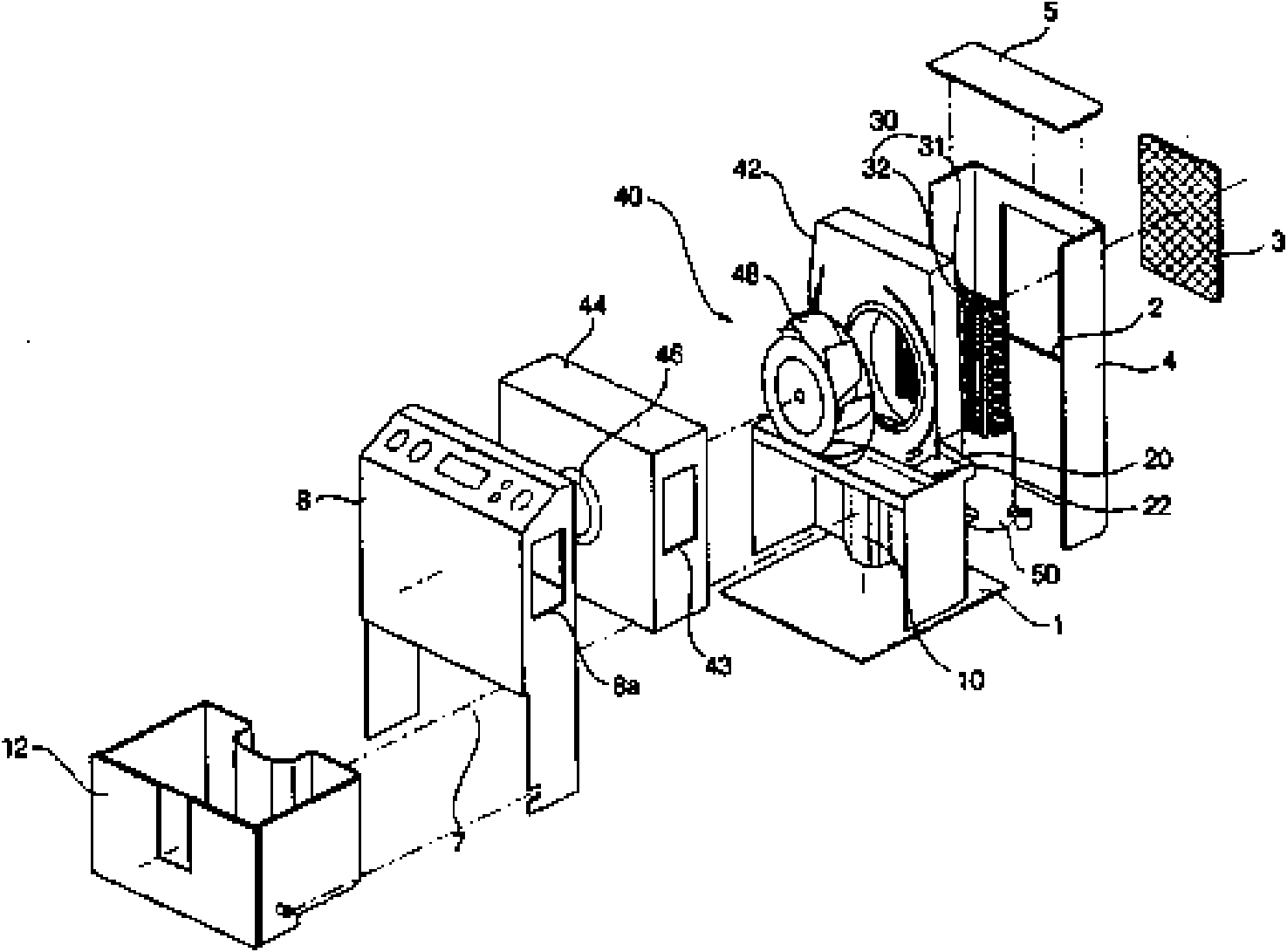
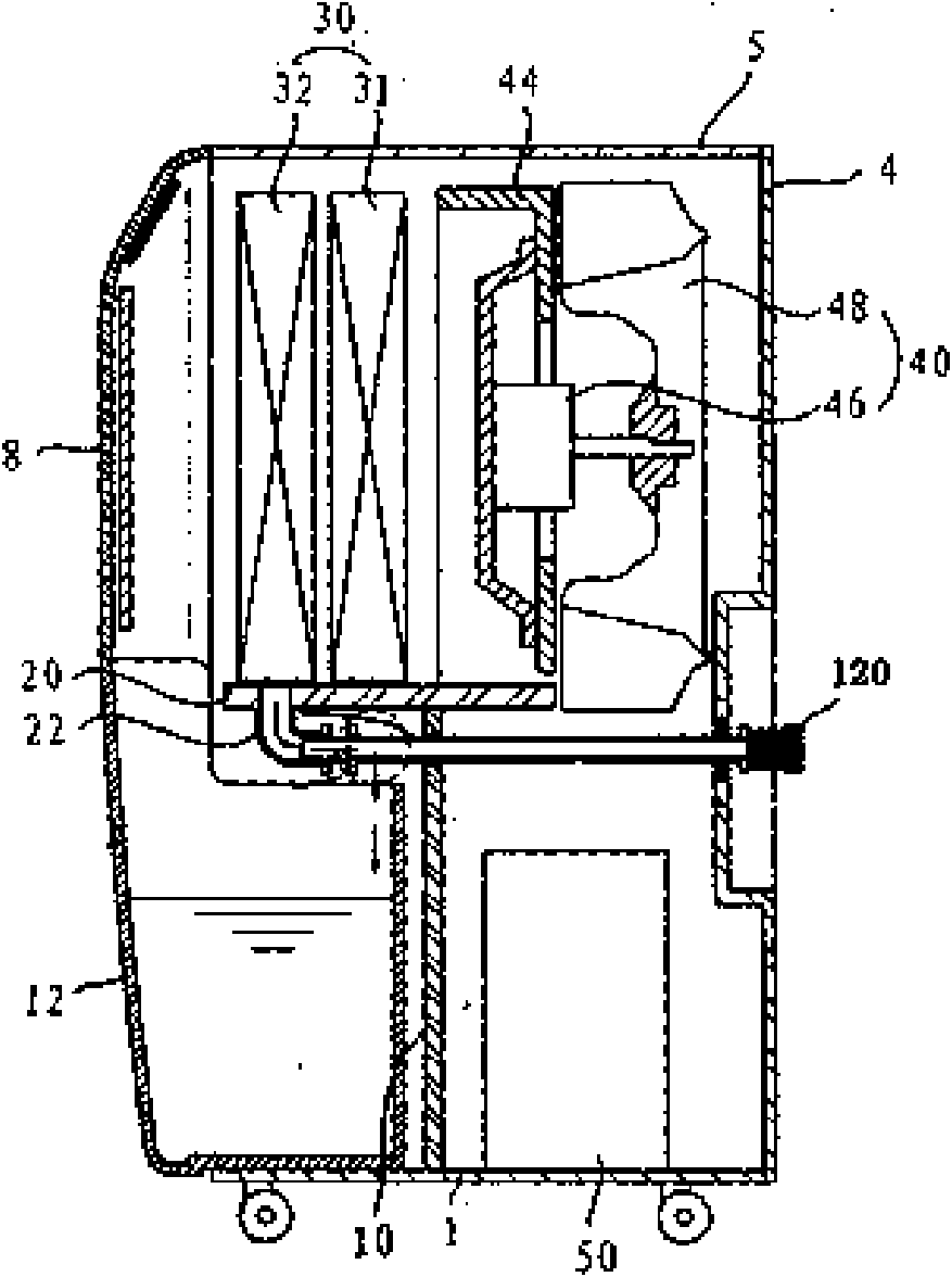
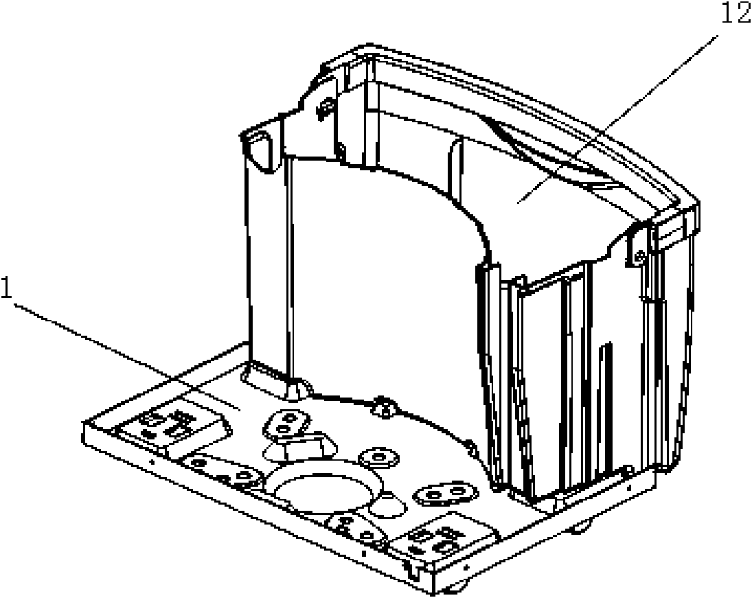
[0029] Figure 4 It is a schematic diagram of the exploded structure of the dehumidifier of the present invention; Figure 5 Is a schematic diagram of the installation position of the guide housing in the dehumidifier of the present invention; Image 6 It is a schematic diagram of the guide housing structure of the dehumidifier of the present invention; Figure 7 It is a plan view of the guide housing of the dehumidifier of the present invention.

[0030] Such as Figure 4 to Figure 7 As shown, in the guide housing structure of the dehumidifier of the present invention, the case 4 forms the appearance of the dehumidifier, contains and protects the various components of the dehumidifier; the evaporator is arranged on the side of the air suction port, and the refrigerant is in the evaporator when the dehumidifier is running Mid-vaporization absorbs heat, so the evaporator ...


PUM


Abstract

The invention relates to a guide shell structure of a dehumidifier. The dehumidifier comprises a case, an evaporator, a condenser, a defrosting tray, a fan, a guide shell, a water tank, a compressor and a base plate, wherein the water tank and the base plate are in an all-in-one structure, and the side wall of the water tank is formed in the way that the base plate extends upwards; a plurality of supporting protuberances are arranged at one side of a front panel on the guide shell towards the case of the dehumidifier, the length of each supporting protuberance is equal to the distance between the guide shell and the inner wall of the front panel, the top of each supporting protuberance is contacted with the inner wall of the front panel, and the front panel is supported by the supporting protuberance. When an external force is applied on the front panel, the supporting protuberances support the front panel to disperse the force applied on the front panel, thus the front panel produces no large deformation, the resistance to deformation of the front panel is improved, the overall structural strength of the case of the dehumidifier is improved, and damage to the front panel caused by bump or collision during transportation is avoided.

Description

technical field [0001] The invention belongs to the technical field of dehumidifiers, and specifically relates to a chassis and a water tank integrally formed, and a plurality of support protrusions supporting the front panel of the chassis are arranged on the guide shell of the fan, thereby improving the strength of the front panel and preventing the front panel from being broken. The boot shell structure. Background technique [0002] Generally speaking, the dehumidifier introduces the humid air in the room into the inside of the chassis, reduces the humidity through a heat exchanger composed of an evaporator and a condenser with refrigerant flow, and then discharges the dehumidified air into the room to reduce the humidity. Device for indoor humidity purposes. [0003] figure 1 It is a schematic diagram of the decomposition structure of the prior art dehumidifier; figure 2 is a side sectional view of a prior art dehumidifier; image 3 It is a structural schematic dia...

Claims


Application Information

Patent Timeline
IPC IPC(8): F24F13/20F24F3/14
Inventor 丹永库鲍长桥
Owner LG ELECTRONICS (TIANJIN) APPLIANCES CO LTD
Why Eureka
Try Eureka