
Method for controlling reaction gas channeling of thermobalance analyzer, and pressurized thermobalance analyzer

A technology for analyzers and thermobalances, applied in the field of pressurized thermobalance analyzers, can solve problems such as slow heating rate, inoperability, and unstable measurement of thermal balances, and achieve the effects of fast heating rate, channeling prevention, and high cost performance

Active Publication Date: 2011-06-29
INST OF PROCESS ENG CHINESE ACAD OF SCI
View PDF5 Cites 28 Cited by
  • Summary
  • Abstract
  • Description
  • Claims
  • Application Information

AI Technical Summary

Problems solved by technology

[0007] The Shanxi Institute of Coal Chemistry, Chinese Academy of Sciences has disclosed a high-temperature thermobalance with a patent number of ZL200620127972.8; although this high-temperature thermobalance is applicable to water vapor (reaction gas), it has a slow heating rate and cannot be used under pressurized conditions. Defects in operation, especially: see figure 1 The schematic diagram of the working principle of the traditional thermobalance analyzer is shown. The protective gas of the high-temperature thermobalance enters from the upper balance protective cover, and enters the reactor through the balance from top to bottom; while the reaction gas participating in the reaction enters from the lower end of the reactor from bottom to bottom. The tail gas that reacts with the sample in the crucible flows out through the tail gas outlet located in the middle of the reactor; during this process, the reaction gas from bottom to top often enters the balance, resulting in unstable measurement of the thermobalance

Method used


Image

  • Method for controlling reaction gas channeling of thermobalance analyzer, and pressurized thermobalance analyzer
  • Method for controlling reaction gas channeling of thermobalance analyzer, and pressurized thermobalance analyzer
  • Method for controlling reaction gas channeling of thermobalance analyzer, and pressurized thermobalance analyzer

Examples


Embodiment 1

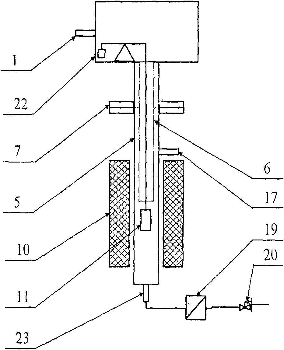
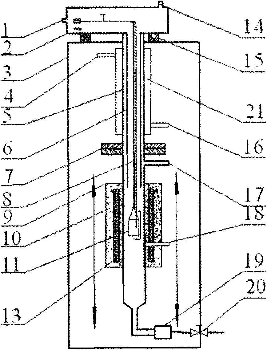
[0054] The pressurized thermobalance analyzer of the present embodiment, its structure comprises:

[0055] The balance in the balance system is a suspended zero balance; one side of the balance cover 2 surrounding the suspended zero balance is provided with a protective gas inlet pipe 1, and the upper end of the balance cover is provided with a data transmission port 14;

[0056] At least one pair of balance supports 15 is installed on the upper surface of a frame-type support 3 whose upper and lower surfaces are horizontal; the balance cover 2 is placed on the upper end of the balance support 15, so that the suspended zero balance is placed in a horizontal state;

[0057] The vertical tubular reactor cavity 5 is composed of upper and lower parts connected by a sealing flange 7;

[0058] The reaction crucible 11 is hoisted in the vertical tubular reactor cavity 5 through the platinum wire connected to the suspended zero balance at the upper end placed vertically; the lower par...


PUM


Abstract

The invention relates to a method for controlling the reaction gas channeling of a thermobalance analyzer, and a pressurized thermobalance analyzer. The method for controlling the channeling comprises the following steps of: introducing protective gas through a balance protective cover at the upper end of the thermobalance analyzer; providing reaction gas through the middle of a reactor cavity; and discharging tail gas through the tail of the reactor cavity. The pressurized thermobalance analyzer comprises a balance system, a reactor system, a vertical moving heating device and a tail gas discharging system which are arranged longitudinally from top to bottom, and is characterized by also comprising an isolation piece concentrically arranged in the reactor cavity, wherein the upper end ofthe isolation piece is connected with the balance protective cover, and the lower end of the isolation piece extends below a sealing flange of the reactor cavity; a gap is reserved between the isolation piece and the outer wall of the reactor cavity; a reaction gas inlet pipe communicated with the gap is arranged on the outer wall of the reactor cavity below the sealing flange; and the bottom of the reactor cavity is communicated with the tail gas discharging system. The method and the pressurized thermobalance analyzer can prevent the reaction gas from channeling, are high in heating rate and are suitable for the reaction atmosphere of air, N2, water vapor, H2 or CO and the like.

Description

technical field [0001] The invention belongs to the field of pressurized thermogravimetric balances, and in particular relates to a method for controlling reaction gas channeling of a thermobalance analyzer and a pressurized thermogravimetric analyzer for rapidly raising the temperature of a water vapor atmosphere. Background technique [0002] Many modern technologies in typical process industries such as energy, chemical industry, materials, metallurgy, and biology involve chemical reactions and physical change processes (such as pressurized gasification, supercritical hydrothermal treatment) that occur under high temperature and high pressure conditions, and some of the processes are in It is realized under special atmosphere conditions such as water vapor, hydrogen, and carbon monoxide. In recent years, high-temperature and high-pressure gasification, synthesis, supercritical science and technology, high-pressure hydrothermal reaction, hydrogen storage and other internat...

Claims


Application Information

Patent Timeline
IPC IPC(8): G01N5/00
Inventor 汪印许光文崔鑫岳君容孙立鑫
Owner INST OF PROCESS ENG CHINESE ACAD OF SCI
Features
  • Generate Ideas
  • Intellectual Property
  • Life Sciences
  • Materials
  • Tech Scout
  • Unparalleled Data Quality
  • Higher Quality Content
  • 60% Fewer Hallucinations
Learn More