Device for synchronously measuring granularity of dynamic light scattering nanometer particles of multi-particles and method thereof

A dynamic light scattering and nano-particle technology, which is applied in the direction of measuring devices, particle size analysis, particle and sedimentation analysis, etc., can solve the problems of complex instrument structure, long sampling time requirements, and low concentration of measured particles, so as to reduce the measurement time Effect

Inactive Publication Date: 2011-06-29
UNIV OF SHANGHAI FOR SCI & TECH
View PDF5 Cites 27 Cited by
  • Summary
  • Abstract
  • Description
  • Claims
  • Application Information

AI Technical Summary

Problems solved by technology

This measurement method has a history of many years and is currently the most important method for measuring nanoparticles. However, there are still some shortcomings. For example, in order to obtain sufficient particle information, the sampling time is very long, the structure of the instrument is complex, and the concentration of the measured particles is required. Very low, resulting in difficulties in sample preparation, etc.

Method used


Image

  • Device for synchronously measuring granularity of dynamic light scattering nanometer particles of multi-particles and method thereof
  • Device for synchronously measuring granularity of dynamic light scattering nanometer particles of multi-particles and method thereof
  • Device for synchronously measuring granularity of dynamic light scattering nanometer particles of multi-particles and method thereof

Examples


Embodiment 1

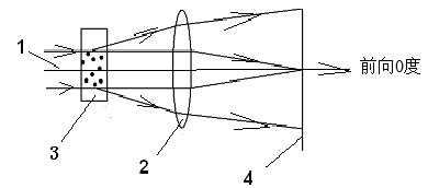
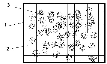
[0058] Depend on figure 1 As shown, the laser beam emitted by the laser source 1 is incident on the sample cell 3, and the particle sample to be measured is placed in the sample cell 3, the particles will scatter the incident laser light, and the scattered light of the particles is collected by the lens 2 and formed on the focal plane of the lens 2 Spatially distributed scattered light points, due to the different sizes of particles and the effect of Brownian motion, the spatially distributed scattered light points will have random changes in intensity and position over time, and this random change in light point intensity and position can be continuously measured An area array photosensitive device 4, such as a CCD or CMOS camera or video camera records, and obtains a sequence of spatially distributed images of continuously changing scattered light points. Due to the Brownian motion and the different sizes of the particles, the scattered light spots at the corresponding posi...

Embodiment 2

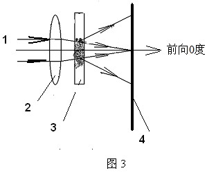
[0062] Such as image 3 As shown, the difference from Example 1 is that the sample cell 3 is arranged behind the receiving lens 2, the laser beam emitted by the laser source 1 first passes through the lens 2 and then enters the sample cell 3, and the dynamic scattered light of the particles is then captured The area array photosensitive device 4, such as a CCD or CMOS camera or video camera, continuously receives and records, and obtains a moving image sequence of continuously changing spatial distribution of scattered light points.

Embodiment 3

[0064] In the optical path where the laser beam 1 , the sample cell 4 , the lens 2 , and the area array photosensitive device 4 are coaxially arranged in Embodiment 1 and Embodiment 2, the size of the entire device is relatively long. To reduce the size of the measuring device, such as Figure 4 As shown, the laser light source 1 is equipped with a Dove prism behind it to reduce the size of the measuring device. The laser beam emitted by the laser light source 1 is rotated 90 degrees by the corner prism, and then enters the lens 2 or the sample cell 3 . Such as Figure 4 As shown, the sample cell 3 is arranged behind the lens 2 . The sample cell 3 can also be arranged in front of the lens 2 .


PUM


Abstract

The invention discloses a device for synchronously measuring granularity of dynamic light scattering nanometer particles of multi-particles and method thereof. The device is characterized by comprising a laser source, a sample pond, a lens and a face array photosensitive element which are coaxially arranged with each other; the method of the invention comprises the following steps: a laser beam radiates on the particles in the sample pond; the particles doing Brownian movement in the sample pond generate dynamic light scattering; dynamic light scattering signals of the particles are collectedafter passing through the lens, and are continuously recorded by the face array photosensitive element to generate continuous movement images of the particles in M amplitude time sequences; and lightspots generated through scattering the particle light on the continuous images form the Brownian movement tracks of the measured particles. The invention can synchronously measure the dynamic light scattering signals of many particles by a face array digital camera and process the dynamic light scattering signals of the particles so as to obtain the particle distribution of the particles and greatly reduce the measuring time; furthermore, the invention can synchronously measure the particles with large distribution range from nanometer to micrometer.

Description

technical field [0001] The invention relates to a particle size measurement device and method based on the principle of dynamic light scattering, in particular to a measurement device and method for continuously detecting the Brownian motion of particles by using an area array photosensitive device to obtain the particle size and distribution of nanometer, submicron and micron particles . Background technique [0002] The most important method of particle measurement is the laser particle size analyzer based on light scattering theory, in which the static scattered light of particles is measured. The basic principle is that when the laser is incident on the particle to be measured, the particle will scatter the incident laser light, and the spatial distribution of the scattered light energy is related to the size of the particle. Measure the spatial distribution of the scattered light energy, and then apply the light scattering theory and inversion algorithm The particle si...

Claims


Application Information

Patent Timeline
Patent Type & Authority Applications(China)
IPC IPC(8): G01N15/02
Inventor 蔡小舒苏明旭
Owner UNIV OF SHANGHAI FOR SCI & TECH
Why Eureka
Try Eureka