

Diaphragm perforating type piezoelectric flat speaker
A perforated, electric plate technology, applied in piezoelectric/electrostrictive transducers, sensors, electrical components, etc., can solve problems such as difficulties and restrict the popularization and application of piezoelectric speakers, and achieve improved flatness and better sound quality. Optimum, the effect of improving stiffness
- Summary
- Abstract
- Description
- Claims
- Application Information
AI Technical Summary
Problems solved by technology
Method used
Image

Examples
Embodiment 1
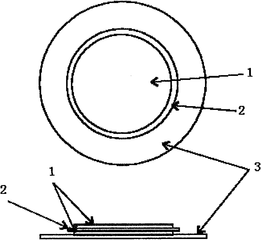
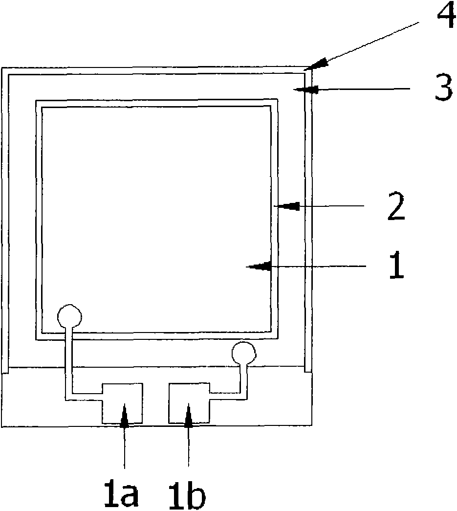
[0047] Figure 3(a) and Figure 3(b) are the front view and exploded view of Embodiment 1 of the present invention. The electrode 1 is divided into a positive electrode and a negative electrode, distributed on the upper surface and the lower surface of the piezoelectric ceramic sheet 2, the piezoelectric ceramic sheet 2 is pasted on the vibrating membrane 3, and the vibrating membrane 3 is restrained and fixed by the frame 4. The positive electrode lead 1a and the negative electrode lead 1b respectively lead the positive electrode and the negative electrode to corresponding solder points on the frame to facilitate connection to external circuits. The diaphragm 3 is made of nickel-iron alloy or stainless steel, and the layer thickness is controlled between 10 microns and 50 microns. A porous array 3a with 5 rectangular holes arranged in an "L" shape is distributed on each of the four corners of the rectangular diaphragm. , and is symmetrical to the center of the diaphragm. The p...
Embodiment 2
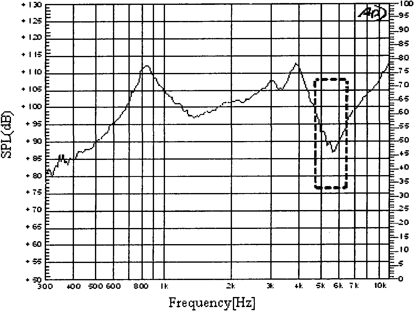
[0049] Figure 5(a) and Figure 5(b) are the front view and exploded view of Embodiment 2 of the present invention. Most of the structure of the piezoelectric speaker of this embodiment is the same as that of Embodiment 1. Only one "L"-shaped strip hole 3a is distributed at each of the four corners of the rectangular diaphragm, and is symmetrical to the center of the diaphragm. attached Figure 6 It is a comparison chart between the frequency response curve of Embodiment 2 of the present invention and the traditional frequency response curve. It can be seen from the figure that when the strip-shaped holes 3a in Embodiment 2 are used, the effect is basically the same as that of the porous array 3a in Embodiment 1, and the distortion in the mid-frequency band is improved, at least increasing the sound pressure level at the distortion place by 10db above. There is almost no change in the other frequency bands of the curve, which maintains the advantages of high sound pressure le...
Embodiment 3
[0051] Figure 7(a) and Figure 7(b) are the front view and exploded view of Embodiment 3 of the present invention. Most of the structure of the piezoelectric speaker of this embodiment is the same as that of Embodiment 1. Only one single hole 3a is distributed at each of the four corners of the rectangular diaphragm, and is symmetrical to the center of the diaphragm. attached Figure 8 It is a comparison chart between the frequency response curve of Embodiment 3 of the present invention and the traditional frequency response curve. It can be seen from the figure that the original mid-frequency distortion disappears, and even the concave curve at the original distortion becomes an upward convex curve, and the sound pressure level increases by more than 25db, which is equivalent to the increase of the voltage applied to the frequency band of the distortion by 16 times. sound pressure level effect. There is almost no change in the low frequency band of the curve, and slight jit...
PUM
 Abstract
Description
Claims
Application Information