Stud flexible welding device and method

A welding device and stud technology, applied in welding equipment, arc welding equipment, manufacturing tools, etc., can solve the problems of inconvenient replacement of automatic nail feeders and affect the efficiency of automatic stud welding, and achieve fast replacement speed and efficiency. Improve and realize the effect of replacement

Active Publication Date: 2011-07-06
NANJING UNIV OF SCI & TECH
View PDF0 Cites 39 Cited by
  • Summary
  • Abstract
  • Description
  • Claims
  • Application Information

AI Technical Summary

Problems solved by technology

When it is necessary to weld studs of various sizes, it is necessary to equip multiple sets of automatic nail feeding machines according to the diameter and length of the studs, and the replacement of the automatic nail feeding machines is inconvenient, which seriously affects the efficiency of automatic stud welding

Method used


Image

  • Stud flexible welding device and method
  • Stud flexible welding device and method
  • Stud flexible welding device and method

Examples


Embodiment 1

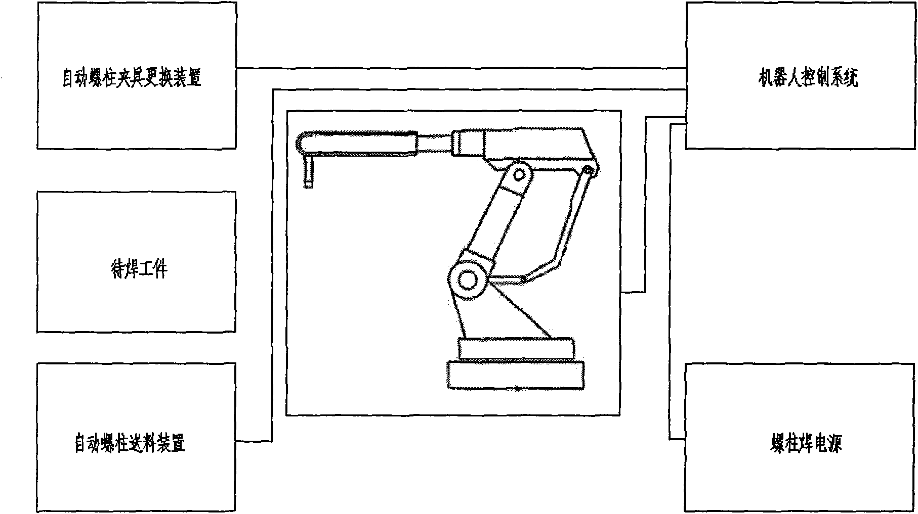
[0051] combine figure 1 , taking the automatic stud welding of a stud with a diameter of 12mm and a length of 60mm and 80mm on a steel plate with a thickness of 20mm as an example. First install the steel studs with a diameter of 12mm and a length of 60mm and 80mm respectively and the ceramic ring matching the studs on the stud fixing plate of the automatic stud feeding device. Then the robot control system sends a series of control signals to complete the entire automatic welding process. The specific steps are as follows: (1) the manipulator moves to the corresponding stage of the automatic stud welding fixture device to install the automatic stud welding fixture device; (2) The manipulator moves to the stud 6 position of the automatic stud feeding device to automatically clamp the stud; (3) The manipulator moves to the designated position to be welded for automatic welding, and completes the entire automatic stud welding process.

Embodiment 2

[0053] combine figure 1 , taking the automatic stud welding of a stud with a diameter of 12 mm and a length of 60 mm and a diameter of 22 mm and a length of 60 mm on a steel plate with a thickness of 20 mm as an example. First, steel studs with a diameter of 12mm and 22mm and the ceramic rings matching the studs are pre-installed on the stud fixing plate of the automatic stud feeding device. Then the robot control system sends out a series of control signals to complete the entire automatic welding process. The specific steps are as follows: (1) The manipulator moves to the stage where the automatic stud welding fixture device matches the stud with a diameter of 12mm, and performs automatic screw welding. Installation of the column welding clamping device; (2) The manipulator moves to the stud 6 position of the automatic stud feeding device to automatically clamp the stud with a diameter of 12mm; (3) The manipulator moves to the designated position to be welded for automatic w...


PUM

PropertyMeasurementUnit
diameteraaaaaaaaaa
lengthaaaaaaaaaa
lengthaaaaaaaaaa

Abstract

The invention discloses a stud flexible welding device and method. The stud flexible welding device comprises a welding robot, a robot control system, an automatic stud welding gun, an automatic stud feeding device, an automatic stud welding and clamping device and an automatic stud welding jig replacing device, wherein the welding robot, the automatic stud welding gun, the automatic stud feeding device, the automatic stud welding and clamping device and the automatic stud welding jig replacing device are connected with the robot control system to receive a control signal of the robot control system; the automatic stud feeding device is used for conveying studs; the automatic stud welding and clamping device is used for setting precompression amount required in an automatic clamping and welding process of studs and ceramic rings; and the automatic stud welding jig replacing device is used for assembling and disassembling the automatic stud welding and clamping device. The invention can be used for carrying out automatic feeding.

Description

technical field [0001] The invention relates to a special welding device and welding method for automatically welding medium and large-sized studs of steel, aluminum, copper, etc. An automatic stud flexible welding device and a welding method for studs of different diameters and different lengths within a range. Background technique [0002] The welding of steel matrix and steel, aluminum, copper studs is widely used in the hull cabin, inside the body of armored vehicles, the inner and outer walls of various pressure vessels, bridges and other fields, and the fields involved in stud welding are becoming more and more extensive. With the rapid development of modern industry, the utilization rate of studs is getting higher and higher, and the number of studs to be welded is also increasing. Modern machinery manufacturing technology requires that stud welding should be fast, reliable, simplified, easy to operate, and reduce costs. [0003] Arc stud welding method (ceramic rin...

Claims


Application Information

Patent Timeline
Patent Type & Authority Applications(China)
IPC IPC(8): B23K9/20B23K9/12
Inventor 王克鸿张德库吴统立
Owner NANJING UNIV OF SCI & TECH
Why Eureka
Try Eureka