Optical cement method for optical element and implementation thereof in pyramid array

A technology of optical components and optical glue, applied in optical components, optics, installation, etc., can solve the problems of unpublished complete metal welding packaging technology, damage to optical components, and scattering effects, and achieve fast optical glue connection and ensure stability. , the effect of avoiding the reflection angle error

Active Publication Date: 2012-06-27
四川欧瑞特光电科技有限公司
View PDF0 Cites 0 Cited by
  • Summary
  • Abstract
  • Description
  • Claims
  • Application Information

AI Technical Summary

Problems solved by technology

This method will produce tiny scratches during pressing and pushing during the bonding process of light and glue, which will damage the optical components, deteriorate the surface finish, and produce scattering effects
[0003] In particular, it refers to the array technology for corner cubes. This technology is still blank in China, and no manufacturer or enterprise has been involved in and produced it. However, the array technology of corner cubes in foreign countries generally adopts the complete metal welding packaging technology, and due to Domestic imports are relatively small, coupled with strong technical confidentiality, so the process of complete metal welding packaging technology has not been announced.
Therefore, the array technology of corner cube prisms has always been a difficult problem to solve, especially more than a certain number of corner cube prism arrays. To ensure the stability of the accuracy of the array pyramid, and need to adapt to different environments, it is more difficult to process

Method used


Image

  • Optical cement method for optical element and implementation thereof in pyramid array
  • Optical cement method for optical element and implementation thereof in pyramid array
  • Optical cement method for optical element and implementation thereof in pyramid array

Examples


Embodiment Construction

[0030] All features disclosed in this specification, or steps in all methods or processes disclosed, may be combined in any manner, except for mutually exclusive features and / or steps.

[0031] Any feature disclosed in this specification (including any appended claims, abstract and drawings), unless expressly stated otherwise, may be replaced by alternative features which are equivalent or serve a similar purpose. That is, unless expressly stated otherwise, each feature is one example only of a series of equivalent or similar features.

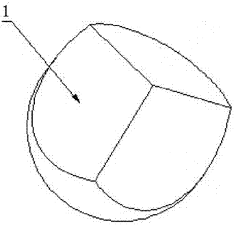
[0032] Corner cube prism 1 among the present invention is as figure 1As shown, the corner cube prism 1 is a cylindrical structure, its bottom is a bottom plane, and its top is three right-angled surfaces, and the angle between any two mutually connected right-angled surfaces is 90°, which can be processed according to actual needs . In the present invention, the surface shape is the definition of flatness in the optical field. In the optical...


PUM

PropertyMeasurementUnit
wavelengthaaaaaaaaaa

Abstract

The invention discloses an optical cement method for an optical element and implementation thereof in a pyramid array, and belongs to the technical field of optical cement of optical elements. The optical cement method for the optical element is implemented by the following steps of: 1) processing an optical element A and an optical element B to meet the optical cement requirement; 2) adhering the two optical elements, putting the two optical elements into vacuum equipment and sealing; 3) vacuumizing, and connecting the planes of the two optical elements by using optical cement; and 4) takingthe two optical elements out integrally. By the optical cement method for the optical element, vacuumizing optical cement connection is performed by the vacuum equipment, so that the bias of the prior art is broken through. The method is simple and high-quality optical cement connection is achieved; furthermore, high surface finish is guaranteed, and the scattering effect and a larger reflection angle error are avoided. By the implementation of the optical cement method in the pyramid array, the reflected surface shape after the array and the reflection angle error meet the high-precision requirement, and the stability of the precision of the array pyramid is guaranteed, so that the method adapts to different environments.

Description

technical field [0001] The invention relates to a photoglue method for optical elements, in particular to a photoglue method for pyramid array products. Background technique [0002] At present, photoresist technology is widely used on optical components, but the existing photoresist technology is mainly: 1. First wipe clean the planes of the two optical components that need photoresist; 2. In one of the optical components A needs Apply a thin layer of vaseline on the surface of the optical glue plane; 3. Put another optical element B on the optical element A, so that the plane of the optical element A that needs the optical glue and the plane of the optical element B that needs the optical glue are bonded; 4. Push the optical element B slightly and press it by hand to expel the air. In this method, in the process of optical glue bonding, tiny scratches will be generated when pressing and pushing, which will damage the optical components, deteriorate the surface finish, and...

Claims


Application Information

Patent Timeline
Patent Type & Authority Patents(China)
IPC IPC(8): G02B7/00G02B7/18
Inventor 王建军
Owner 四川欧瑞特光电科技有限公司
Why Eureka
Try Eureka