Supercharge Your Innovation With Domain-Expert AI Agents!

Optical image amplification device and image display system

An optical image and magnifying device technology, applied in optics, magnifying glass, optical components, etc., can solve problems such as difficulty in ensuring the clarity of magnified images, pixel overlap and stray, and is not conducive to thinning and thinning display devices, and achieves small thickness, Not easy to deform, light and thin to ensure the effect

Inactive Publication Date: 2012-12-26
GUANGDONG VTRON TECH CO LTD
View PDF8 Cites 0 Cited by
  • Summary
  • Abstract
  • Description
  • Claims
  • Application Information

AI Technical Summary

Problems solved by technology

For large-area optical images, using this conventional method for optical amplification is not conducive to the thinning and lightening of display devices
Although it is more feasible to use a Fresnel lens to magnify a large-area optical image, it has relatively high requirements for the image display device, requiring the light emitted by the image display device to be collimated light, otherwise there will be overlap between pixels Stray, it is difficult to ensure the clarity of the enlarged image

Method used


Image

  • Optical image amplification device and image display system
  • Optical image amplification device and image display system
  • Optical image amplification device and image display system

Examples


Embodiment Construction

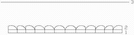
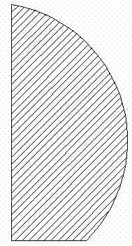
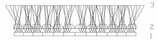
[0016] Such as figure 1 As shown, the optical image magnification device of this embodiment includes an off-center microlens array 2, and when the optical image magnification device 2 is stacked closely on the display device 1, an image display system can be formed. And the aperture size of each eccentric microlens of the eccentric microlens array 2 is consistent with the size of one or more pixels of the display device 1, and the center position of each eccentric microlens is consistent with the center position of one or more pixels of the display device 1 . The eccentric microlens array 2 is arranged in such a way that the eccentricity of the eccentric microlenses gradually increases from the middle of the array to the surroundings. That is to say, the eccentricity of the eccentric microlenses located in the eccentric microlens array 2 gradually increases from the inside to the outside. Moreover, the eccentricity of each eccentric microlens is determined by the magnificati...


PUM


Abstract

The invention belongs to the field of optical image amplification, and particularly relates to an optical image amplification device. The optical image amplification device comprises an eccentric microlens array arranged on a display device; the caliber size of each eccentric microlens in the eccentric microlens array is consistent to the size of one or more pixels of the display device; or the caliber of the plurality of microlenses is consistent to the size of one pixel, and the central position of each eccentric microlens is consistent to the central position of one or more pixels of the display device; or the central position of the plurality of microlenses is consistent to the central position of one pixel of the display device. By adopting the device, the large-area optical image can be amplified, and furthermore, the definition of the amplified image and the thinning of the display device can be ensured. Furthermore, the invention also discloses an image display system with the optical image amplification device.

Description

technical field [0001] The invention belongs to the field of optical image enlargement, in particular to an optical image enlargement device and an image display system with the device. Background technique [0002] How to optically magnify a large-area display image has become a research hotspot. The general optical image magnification method is to use an optical lens to magnify the image. There is a certain distance between the optical image and the lens, and the aperture of the optical lens is much larger than the optical image. For a large-area optical image, using this conventional method for optical amplification is not conducive to the thinning of the display device. Although it is more feasible to use a Fresnel lens to magnify a large-area optical image, it has relatively high requirements for the image display device, requiring the light emitted by the image display device to be collimated light, otherwise there will be overlap between pixels Stray, it is difficul...

Claims


Application Information

Patent Timeline
Patent Type & Authority Patents(China)
IPC IPC(8): G02B25/00G02B3/00
Inventor 彭晓林黄永峰
Owner GUANGDONG VTRON TECH CO LTD
Features
  • R&D
  • Intellectual Property
  • Life Sciences
  • Materials
  • Tech Scout
  • Unparalleled Data Quality
  • Higher Quality Content
  • 60% Fewer Hallucinations
Learn More