Gas-oil-water three-phase separator
A three-phase separator, gas-oil-water technology, applied in the direction of liquid separation, separation method, liquid degassing, etc., can solve the problems of high oil content, bulky, unsatisfactory separation effect, etc., achieve ideal effect, save maintenance work Effect
- Summary
- Abstract
- Description
- Claims
- Application Information
AI Technical Summary
Problems solved by technology
Method used
Image
Examples
Embodiment 1
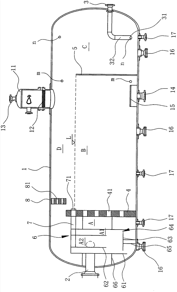
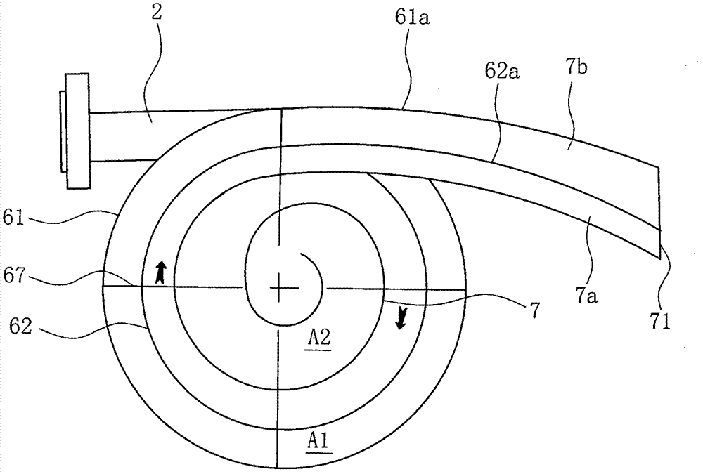
[0036] Such as figure 1 , figure 2 As shown, the gas-oil-water three-phase separator includes a horizontal tank body 1, a crude oil input pipe 2 and an oil discharge pipe 3;
[0037] Wherein, the interior of the tank body 1 is erected with a liquid stabilizing plate 4 and a baffle plate 5 in sequence from left to right, and the interior of the tank body 1 is divided into a separation area A, a liquid collection area B and an oil collection area in sequence from left to right. In zone C, the top of the liquid stabilizing plate 4 is higher than the baffle 5, and there is a gap between the tops of the liquid stabilizing plate 4 and the baffle 5 and the top of the tank 1, and the inside of the tank 1 is at the top of the baffle 5. A gas gathering area D is formed above;
[0038] The bottom of the tank body 1 is provided with a drainage pipe 14 at the position where the liquid collection area B is located and on the left side of the baffle plate 5;
[0039] The top of the tank bo...
Embodiment 2
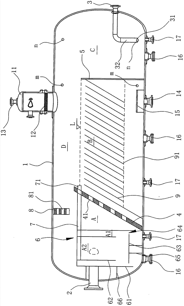
[0059] Such as image 3 As shown, the difference between Embodiment 2 of the present invention and Embodiment 1 is that: the liquid stabilizing plate 4 is inclined in such a way that the top is inclined to the right, and there are multiple parallel and spaced plates in the liquid collection area B. The corrugated plate 9 forms a corrugated plate group, the bottom of the corrugated plate closest to the liquid steady flow plate 4 in the corrugated plate group is in contact with the bottom of the tank body 1, and the corrugated plate group is supported and fixed by a bracket 91 arranged at the bottom. In this embodiment, the corrugated plate 9 is also parallel to the liquid stabilizing plate 4 .
[0060] The liquid phase will pass through the corrugated plate 9 from top to bottom and enter the bottom area of the tank 1, the oil phase will naturally float on the top of the liquid collection area B, and the water phase will be discharged from the tank 1 through the drain pipe 14....
PUM
 Abstract
Description
Claims
Application Information
 - R&D
- Intellectual Property
- Life Sciences
- Materials
- Tech Scout
- Unparalleled Data Quality
- Higher Quality Content
- 60% Fewer Hallucinations
Browse by: Latest US Patents, China's latest patents, Technical Efficacy Thesaurus, Application Domain, Technology Topic, Popular Technical Reports.
© 2025 PatSnap. All rights reserved.Legal|Privacy policy|Modern Slavery Act Transparency Statement|Sitemap|About US| Contact US: help@patsnap.com


