
High-speed precise electric spindle cooling system

A cooling system and motorized spindle technology, applied in cooling/ventilation devices, electromechanical devices, electrical components, etc., can solve the problems of not being able to cool and lubricate bearings, increase bearing preload, and aggravate bearing heating, etc. The effect of machining accuracy error, improving service life and ensuring temperature stability

Inactive Publication Date: 2011-07-13
DONGGUAN UNIV OF TECH
View PDF4 Cites 50 Cited by
  • Summary
  • Abstract
  • Description
  • Claims
  • Application Information

AI Technical Summary

Problems solved by technology

In addition, the coolant used to cool the bearing cannot be distributed to the inner ring and shaft core of the bearing under the centrifugal force of the high-speed rotating spindle. As the temperature rise of the spindle increases, the preload of the bearing will increase. In turn, it will aggravate the heating of the bearing, so that the bearing cannot be effectively cooled and lubricated

Method used


Image

  • High-speed precise electric spindle cooling system
  • High-speed precise electric spindle cooling system

Examples


Embodiment Construction

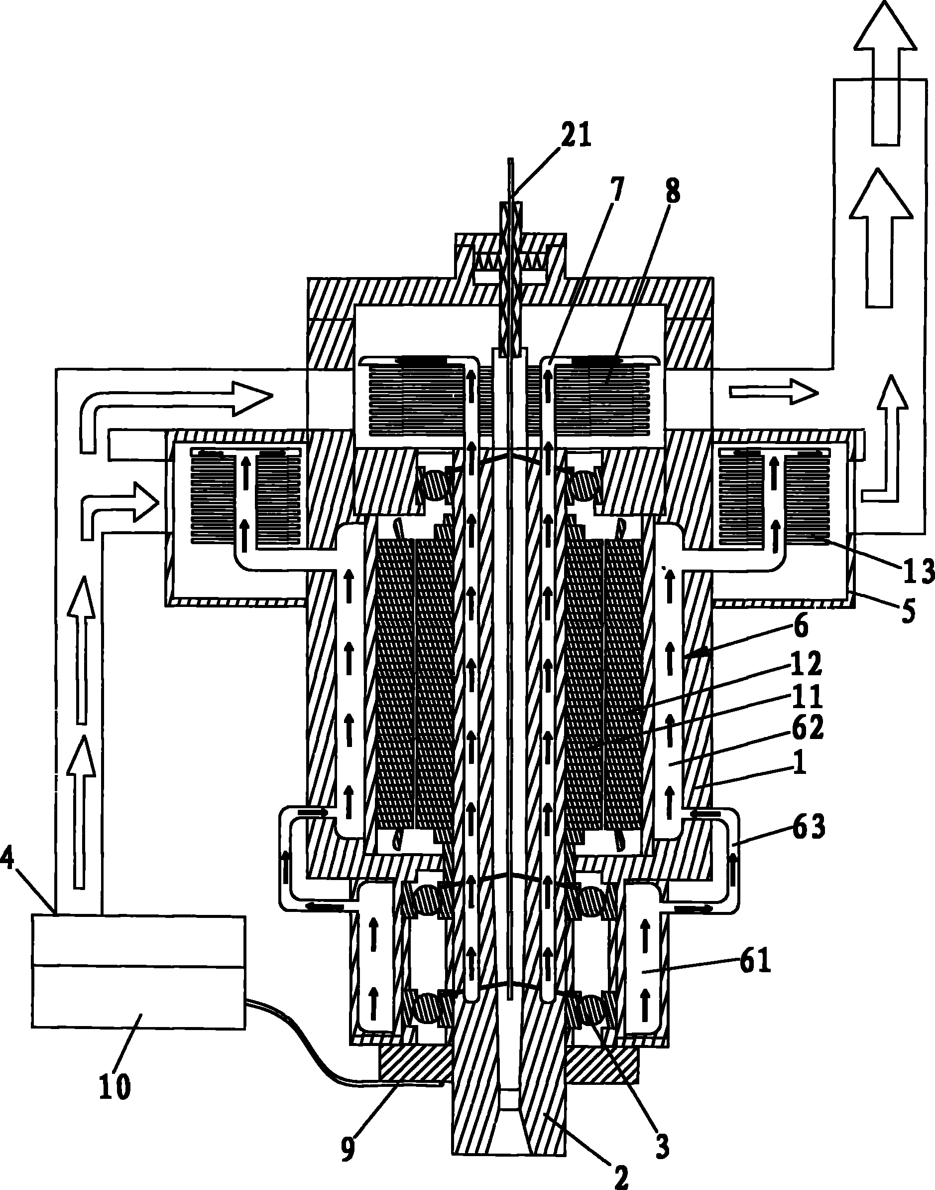
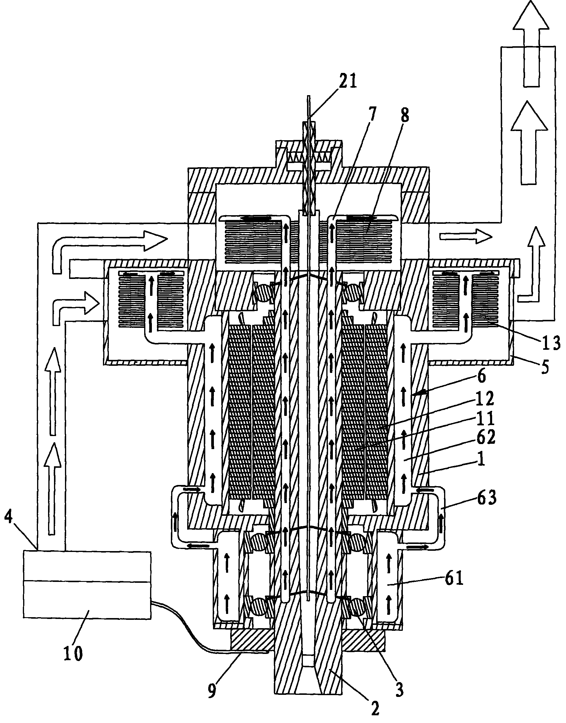
[0015] Below in conjunction with accompanying drawing, the present invention will be further described, see figure 1 As shown, the high-speed precision electric spindle cooling system of the present invention includes an electric spindle housing 1, an electric spindle core 2, a rotor 11, a stator 12, and a cooling air conditioner 4, and the two ends of the electric spindle core 2 are rotatably connected by bearings 3 In the motorized spindle housing 1, the rotor 11 is sleeved on the motorized spindle shaft core 2, the stator 12 is fixed inside the motorized spindle housing 1, the rear end of the motorized spindle housing 1 is provided with an annular cooling seal cover 5, and the annular cooling seal The cover 5 communicates with the cooling gas output port of the cooling air conditioner 4. The electric spindle housing 1 is provided with a housing heat pipe 6. The evaporation end of the housing heat pipe 6 extends to the front bearing 3, and the condensation end of the housing ...


PUM


Abstract

The invention relates to the technical field of an electric spindle, in particular to a high-speed precise electric spindle cooling system which comprises an electric spindle shell cooling part, an electric spindle core cooling part and a bearing spindle core lubricating / cooling part, wherein when the electric spindle works, the temperature rise change can be controlled within + / -1 DEG C. The concrete scheme is as follows: a ring sleeve type heat pipe cooling mode is arranged at the electric spindle shell part, and the heat of the shell is taken away quickly by increasing the cooling contact surface; the spindle core cooling part is provided with symmetrical bar-type heat pipes which are uniformly distributed on the spindle core, and the spindle core is cooled by use of the high-speed conductivity and homoiothermy of the heat pipes; and a spindle core liquid lubricating / cooling mode is adopted at the bearing lubricating / cooling part, and makes full use of the high rotation speed of the high-speed electric spindle to generate centrifugal force so that the lubricating / cooling liquid is uniformly distributed on the bearing roller. The temperature stability of the electric spindle can be ensured, the processing precision error caused by thermal expansion of the electric spindle is minimized, and the service life of the spindle and the spindle bearing can be prolonged at the same time.

Description

Technical field: [0001] The invention relates to the technical field of electric spindles, in particular to a high-speed precision electric spindle cooling system. Background technique: [0002] At present, with the rapid development and improvement of electric drive technology (frequency conversion speed regulation technology, motor vector control technology, etc.), the mechanical structure of the main drive system of high-speed CNC machine tools has been greatly simplified, basically canceling the pulley drive and gear drive. The main shaft of the machine tool is directly driven by the built-in motor, so that the length of the main transmission chain of the machine tool is shortened to zero, and the "zero transmission" of the machine tool is realized. This type of transmission structure in which the spindle motor and the machine tool spindle are "integrated into one" makes the spindle components relatively independent from the transmission system and the overall structure...

Claims


Application Information

Patent Timeline
IPC IPC(8): B23B19/02B23Q11/12H02K5/20H02K5/18H02K9/20
Inventor 许光辉邓君钟守炎黄泳波赖树明林朝阳叶智方徐素武徐红娇罗剑英
Owner DONGGUAN UNIV OF TECH
Learn More