Square or flat material production line jet cooling system

A cooling system and production line technology, applied in furnaces, heat treatment equipment, quenching devices, etc., can solve problems such as oil quenching environment problems

Active Publication Date: 2011-07-13
UNIV OF SCI & TECH BEIJING
View PDF4 Cites 23 Cited by
  • Summary
  • Abstract
  • Description
  • Claims
  • Application Information

AI Technical Summary

Problems solved by technology

For pool quenching and controlled cooling, it is still difficult to ensure uniform

Method used


Image

  • Square or flat material production line jet cooling system
  • Square or flat material production line jet cooling system
  • Square or flat material production line jet cooling system

Examples


Embodiment 1

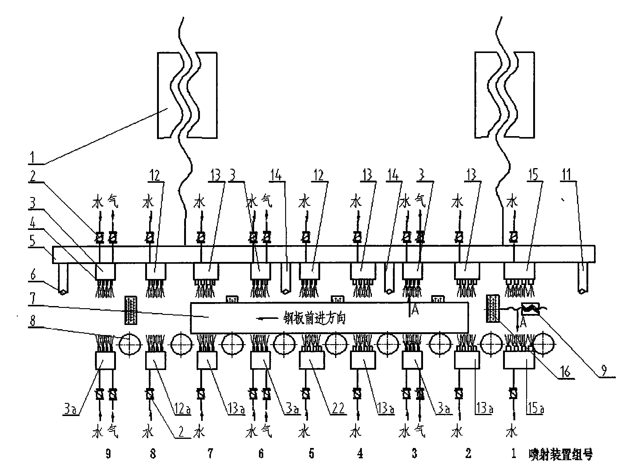
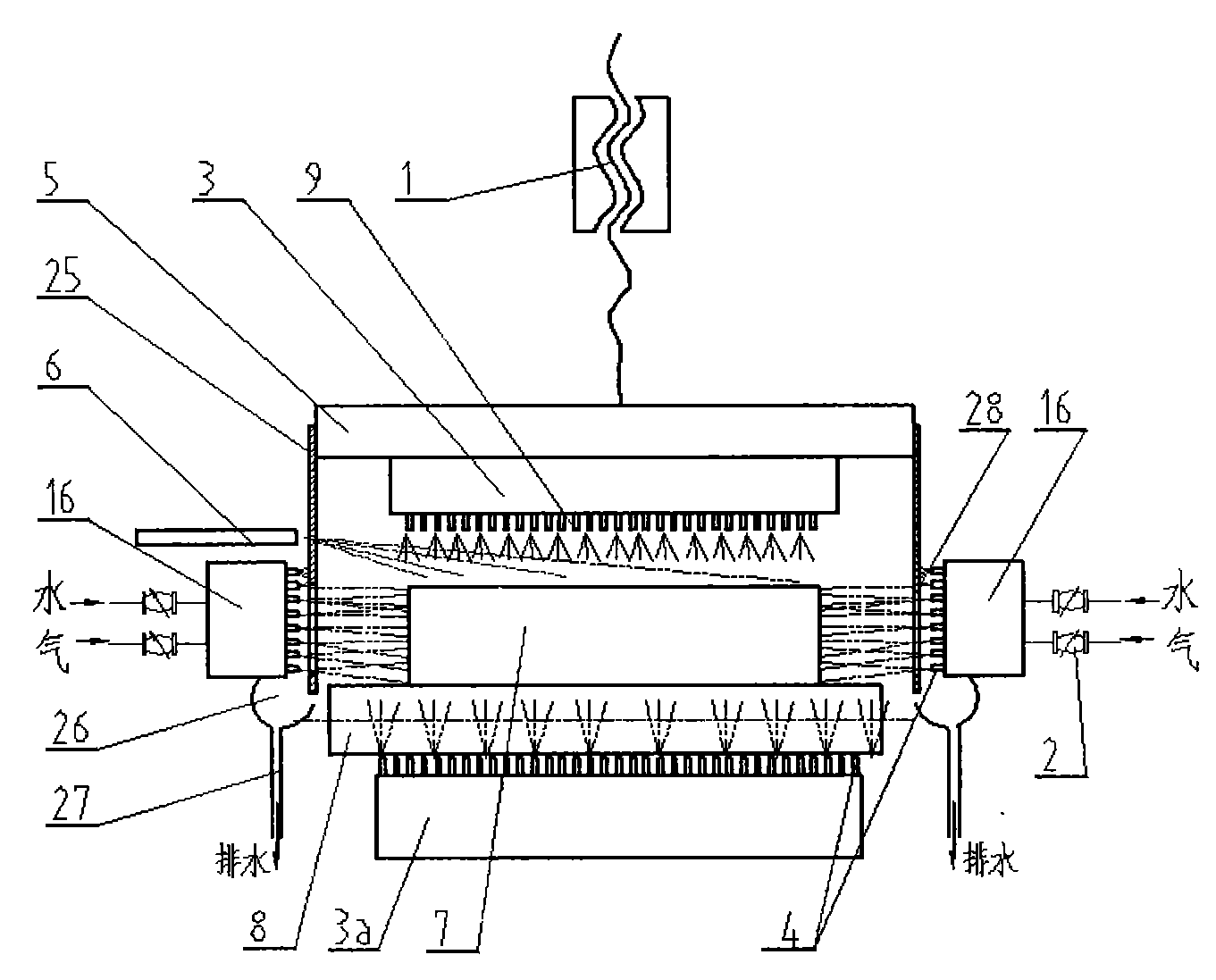
[0012] see figure 1 , The spray cooling system of the square flat material production line is mainly composed of: 1 set of upper and lower strong cooling spray devices, namely 15 and 15a; 3 sets of upper and lower intermediate cooling spray devices, namely 13 and 13a; 2 sets of upper and lower weak cooling spray devices, namely 12 and 12a ; 3 groups of upper and lower aerosol spraying devices, namely 3 and 3a; 5 groups of side cooling spraying devices 16, and 3 purging devices 11, 14, 6 are respectively located at the entrance, middle and exit of the production line. The upper and lower cooling injection devices are installed between two adjacent roller tables 8, the upper strong cooling is to the lower strong cooling, the upper middle cooling is to the lower middle cooling, the upper weak cooling is to the lower weak cooling, and the upper air mist is to the lower air mist, one by one correspond. The order of arrangement of strong, medium and weak aerosol spraying is (viewed...

Embodiment 2

[0019]The preparation for heat treatment is a solid stainless steel plate 1Cr18Ni9Ti with a thickness of 10mm. The equipment is the same as in Example 1. Lift the upper jet cooling device so that the nozzle is 280mm above the upper surface of the roller table 7. Turn on the 2nd group of medium cooling spray, the 3rd group of aerosol, the 5th group of weak cooling, the 8th group of weak cooling and the 9th group of aerosol. The valve opening degree of the second group of strong cold flow control device is 80%; the third group of aerosol spray device, the water valve opening degree of the flow control device is 60%, and the air is 70%; the fifth group of weak cold flow control device The water valve opening degree is 80% %; the opening degree of the water valve of the weak cold flow control device of the 8th group is 40%; the opening degree of the water valve of the flow control device of the 9th group is 30% and the gas is 80%. Due to the thinness of the square flat material,...


PUM


Abstract

The invention relates to square or flat material production line jet cooling thermal treatment equipment, which mainly consists of upper and lower strong cold jet devices (15 and 15a), upper and lower medium cold jet devices (13 and 13a), upper and lower weak cold jet devices (12 and 12a), upper and lower aerosol jet devices (3 and 3a), side cold jet devices (16), front, middle and rear blowing devices (11, 14 and 6), a flow control device (2) and an upper jet device lifting device (1), wherein the upper strong, medium and weak jet devices (15, 13 and 12), the upper aerosol jet devices (3) and the front, middle and rear blowing devices (11, 14 and 6) can lift up and down together with the lifting device (1) so as to adapt to the requirements of square or flat materials of different thicknesses. The side cold jet devices (16) are arranged on two sides of a rail (8), and can quickly cool the thick square or flat materials. The cooling capacity of the cooling system can be regulated by opening the jet cooling devices of different groups and regulating the flow control device (2). Front and rear staggered nozzles dense in the middle and sparse on two sides are arranged so that the jet cooling system is uniform and the quenched square or flat materials have low deformation, unique texture and no cracking.

Description

technical field [0001] The invention relates to metal heat treatment equipment for metallurgical machinery, in particular to an online heat treatment equipment for square or flat materials. technical background [0002] When high-temperature square or flat metal is cooled and quenched, offline quenching is mostly used, that is, the high-temperature square and flat material is cooled in a water pool, oil pool or air. This off-line quenching requires a large amount of energy to heat the material to be quenched. For pool quenching and controlled cooling, it is still difficult to ensure uniform quenching and controlled cooling, and oil quenching also has environmental problems. [0003] The object of the present invention is to provide an on-line continuous quenching heat treatment equipment, regardless of the thickness of the square flat material in the process of advancing on the roller table, the spray cooling system with adjustable cooling capacity can uniformly cool the sq...

Claims


Application Information

Patent Timeline
IPC IPC(8): C21D9/00C21D1/667
Inventor 边新孝李谋渭张少军刘国勇朱冬梅
Owner UNIV OF SCI & TECH BEIJING
Why Eureka
Try Eureka