Cathode boss structure of aluminum electrolysis cell

A boss structure, aluminum electrolytic cell technology, applied in the field of aluminum electrolysis, can solve the problems of reduced electrochemical reaction efficiency, increased noise value of electrolytic cell, unstable electrolyte system, etc., to reduce electrochemical corrosion and reduce aluminum production. , the effect of reducing the backlog of funds

Inactive Publication Date: 2011-07-13
GUIYANG AL-MG DESIGN & RES INST
View PDF2 Cites 7 Cited by
  • Summary
  • Abstract
  • Description
  • Claims
  • Application Information

AI Technical Summary

Problems solved by technology

[0003] At present, the linings of large-scale prebaked anode electrolytic cells at home and abroad are arranged vertically with cathodes of the same specification, and the top surfaces of all cathodes are on the same level. During normal production, due to the action of electromagnetic force, the aluminum liquid layer in the electrolytic cell is always at Flow state, flow field such as Figure 5 , electrolyte flow, especially irregular flow, is one of the main reasons for the instability of the electrolytic cell. The reasons are as follows: ① The electrolyte system is unstable, which reduces the efficiency of the electrochemical reaction; Voltage to control low noise, both of the above two points lead to an increase in power consumption per ton of aluminum
With the development of large-scale capacity, the furnace and current of the electrolytic cell are getting larger and larger, resulting in the following flow field problems becoming more and more serious: the probability of uneven distribution of temperature and various materials in the electrolyte in the cell increases; The liquid flow rate increases; the amount of aluminum being produced in the tank increases; the possibility of turbulent flow of the molten fluid in the tank increases at some positions

Method used


Image

  • Cathode boss structure of aluminum electrolysis cell
  • Cathode boss structure of aluminum electrolysis cell
  • Cathode boss structure of aluminum electrolysis cell

Examples


Embodiment Construction

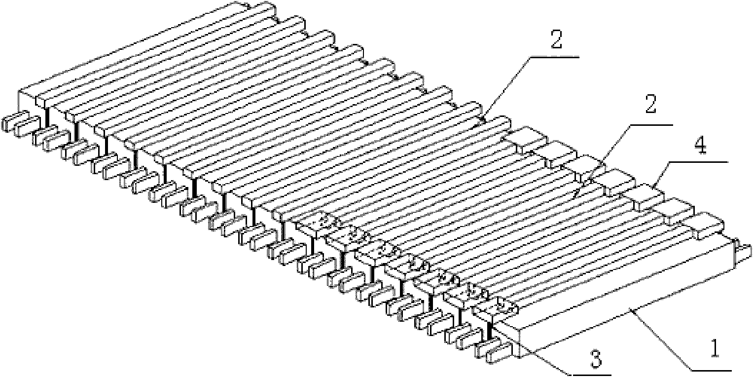
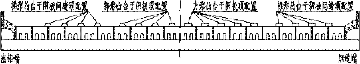
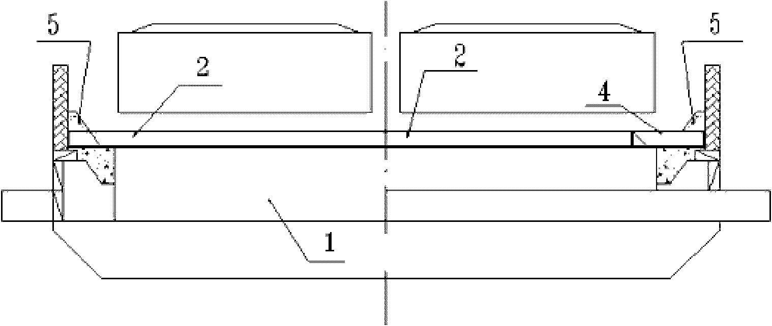
[0024] Embodiments of the present invention: as figure 1 , 2 , 3, it mainly includes: cathode carbon block 1, cathode boss 2, restraint carbon block 4, cathode boss 2 is placed on the top surface of the cathode carbon block 1 of the electrolytic cell, or placed on the cathode gap 3, The distance between the cathode bosses is in the range of 400mm to 900mm, and it can be arranged sparsely or densely according to different groove types.

[0025] There are two ways to implant the cathode boss 2 . Method 1: The cathode boss with a long structure is 100-250mm longer than the cathode carbon block, and the two ends are directly embedded in the paste 5 around the side; Method 2: The cathode boss of the mosaic butt joint type has a length of Within the range of 3000-3200mm, the two ends are respectively fixed with constrained carbon blocks 4, and the constrained carbon blocks are embedded in the paste 5 around the side.

[0026] The cross-section of the cathode boss 2 is a rectangl...


PUM

PropertyMeasurementUnit
lengthaaaaaaaaaa
heightaaaaaaaaaa
widthaaaaaaaaaa

Abstract

The invention discloses a cathode boss structure of an aluminum electrolysis cell. Cathode bosses (2) are arranged on top surfaces of cathode carbon blocks (1) or are arranged on joint gaps (3) between every two cathode carbon blocks (1); the space between every two cathode bosses is between 400mm and 900mm; the full-length cathode bosses are 100mm to 250mm longer than the cathode carbon blocks, and the two end heads of the full-length cathode bosses are directly embedded in surrounding paste (5) on lateral parts; the mosaic butted cathode bosses have lengths of between 3,000mm and 3,200mm, the two end heads of the mosaic butted cathode bosses are fixed by using limiting carbon blocks (4) respectively, and the limiting carbon blocks are embedded in the surrounding paste (5) on the lateral parts; and the sections of the cathode bosses are of an oblong or isosceles trapezoid. The structure is suitable for all electrolysis cells at present. When an edge of a normal electrolysis cell is firmly bound, strip-shaped bosses are conveniently and quickly implanted into the upper surface of a cathode of the electrolysis cell to form a flow reduction effect, so that the flow velocity of a molten aluminum layer is reduced, energy dissipation of the molten aluminum layer is reduced, production stability of the electrolysis cell is enhanced, and energy consumption is reduced.

Description

technical field [0001] The invention relates to a tank lining cathode boss structure applied to an aluminum electrolytic tank, and belongs to the technical field of aluminum electrolysis. Background technique [0002] In the past 10 years, my country's electrolytic aluminum technology with aluminum electrolytic cells as the core has been fully developed, and basically realized the serialization of electrolytic cell capacity (200KA, 300KA, 400KA, etc.), and the large-scale electrolytic series (from 100,000 tons to 250,000 tons). However, aluminum electrolysis is a typical high-energy-carrying industry, and the comprehensive power consumption per ton of aluminum is generally above 14,000 kwh / t-Al. Based on the national production capacity of 15 million tons of primary aluminum in 2008, the total energy consumption of my country's electrolytic aluminum industry should be 2,100 kwh per year. More than 100 million degrees. The energy utilization rate of electrolytic aluminum prod...

Claims


Application Information

Patent Timeline
Patent Type & Authority Applications(China)
IPC IPC(8): C25C3/08
CPCC25C7/02C25C3/08
Inventor 曹斌杨涛
Owner GUIYANG AL-MG DESIGN & RES INST
Why Eureka
Try Eureka