
Differential type plastering device

A differential and control device technology, which is applied in the direction of construction and building construction, can solve the problems of heavy operation, large manpower occupation, uneven thickness of mortar, etc., achieve good combination, realize continuous work, and improve plastering efficiency Effect

Inactive Publication Date: 2011-07-13
HEBEI UNIVERSITY OF SCIENCE AND TECHNOLOGY
View PDF5 Cites 9 Cited by
  • Summary
  • Abstract
  • Description
  • Claims
  • Application Information

AI Technical Summary

Problems solved by technology

[0002] Wall plastering is one of the most labor-intensive tasks in building construction. At present, the manual plastering work mode is still widely used at home and abroad. The quality and efficiency of manual plastering depend to a large extent on the worker's operation technology and quality. According to supervision requirements, people have been working on the mechanization of wall plastering for a long time to shorten the construction period and reduce labor costs. So far, more than 200 patents have appeared, but these patents are not actually implemented. According to some of the patents The trial-manufactured plastering equipment generally employs a large number of people, loses a lot of ash, and is cumbersome to operate. The thickness of the mortar on the wall is uneven, and it is difficult to hang the plaster. At the same time, because these plastering machines are difficult to determine the amount of plastering according to the unevenness of the wall and compact it like manual plastering, the mortar and the wall are generally not firmly combined. , it is difficult to be accepted by users, which greatly limits the productization of its prototype and the promotion of corresponding technologies. How to better simulate the mechanized plastering device of the manual plastering process has always been a difficult problem faced by construction engineering technicians

Method used


Image

  • Differential type plastering device
  • Differential type plastering device
  • Differential type plastering device

Examples


Embodiment Construction

[0020] The present invention will be further described in detail below in conjunction with the accompanying drawings.

[0021] see figure 1 , figure 2 , image 3 , Figure 4 .

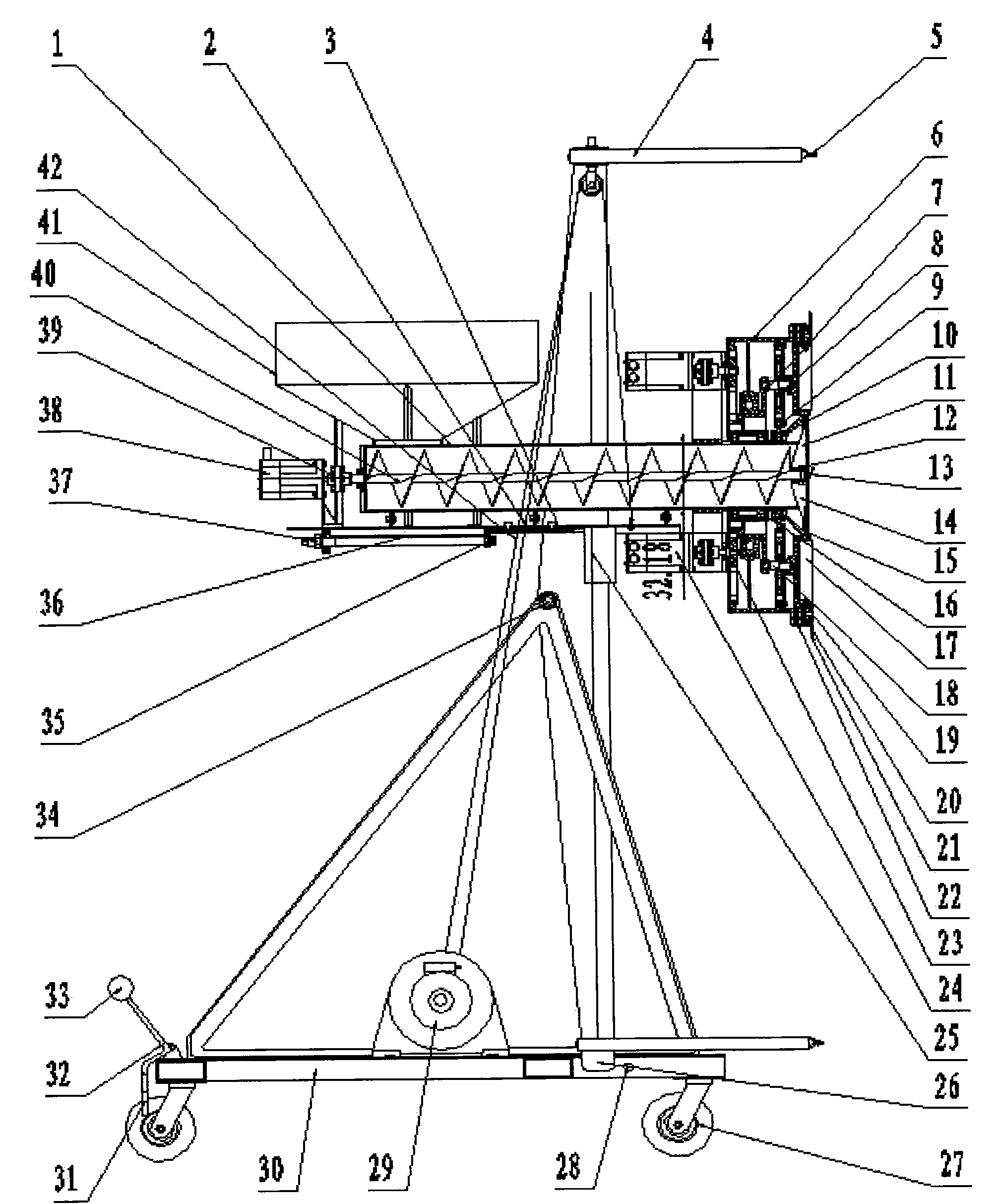
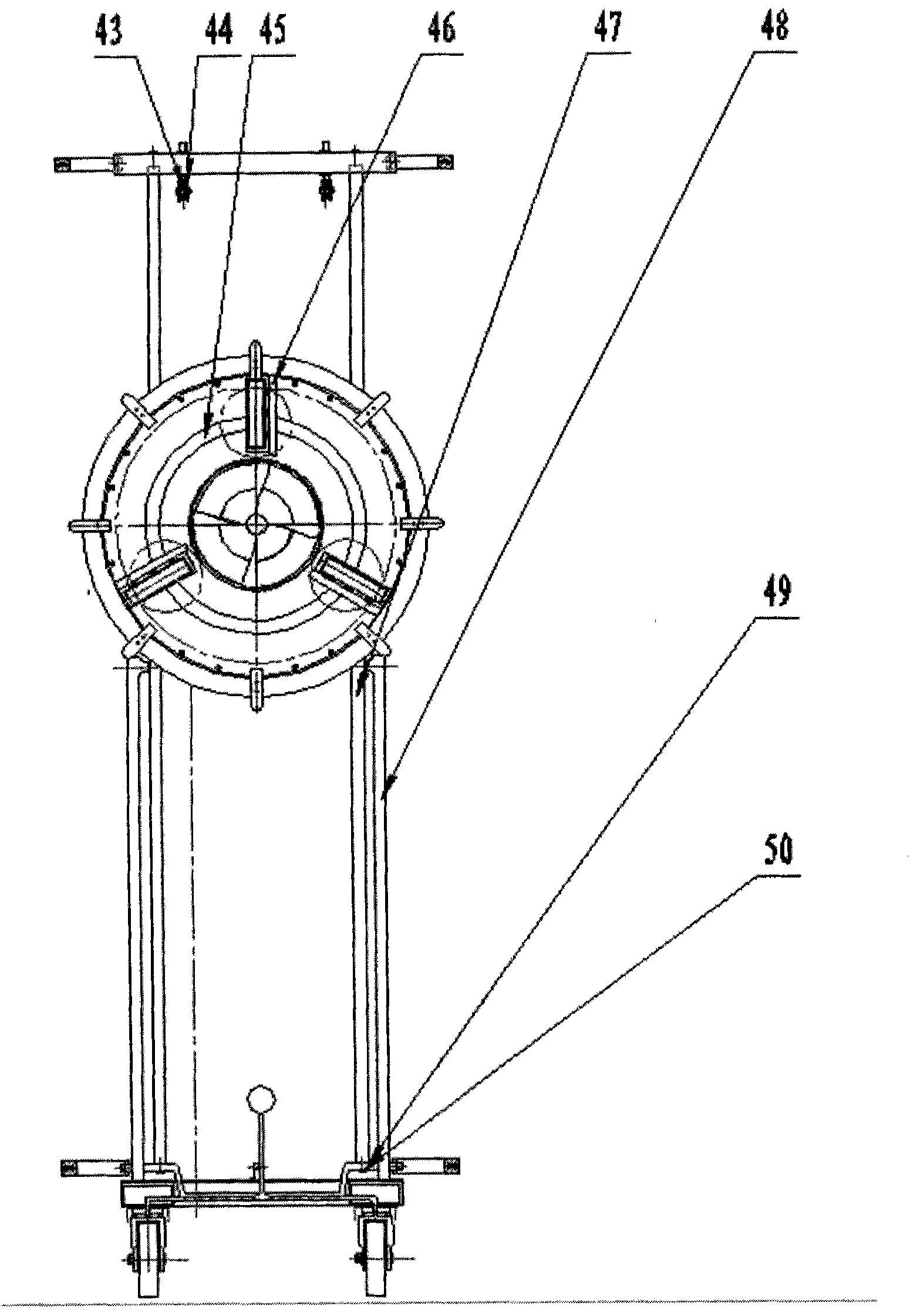
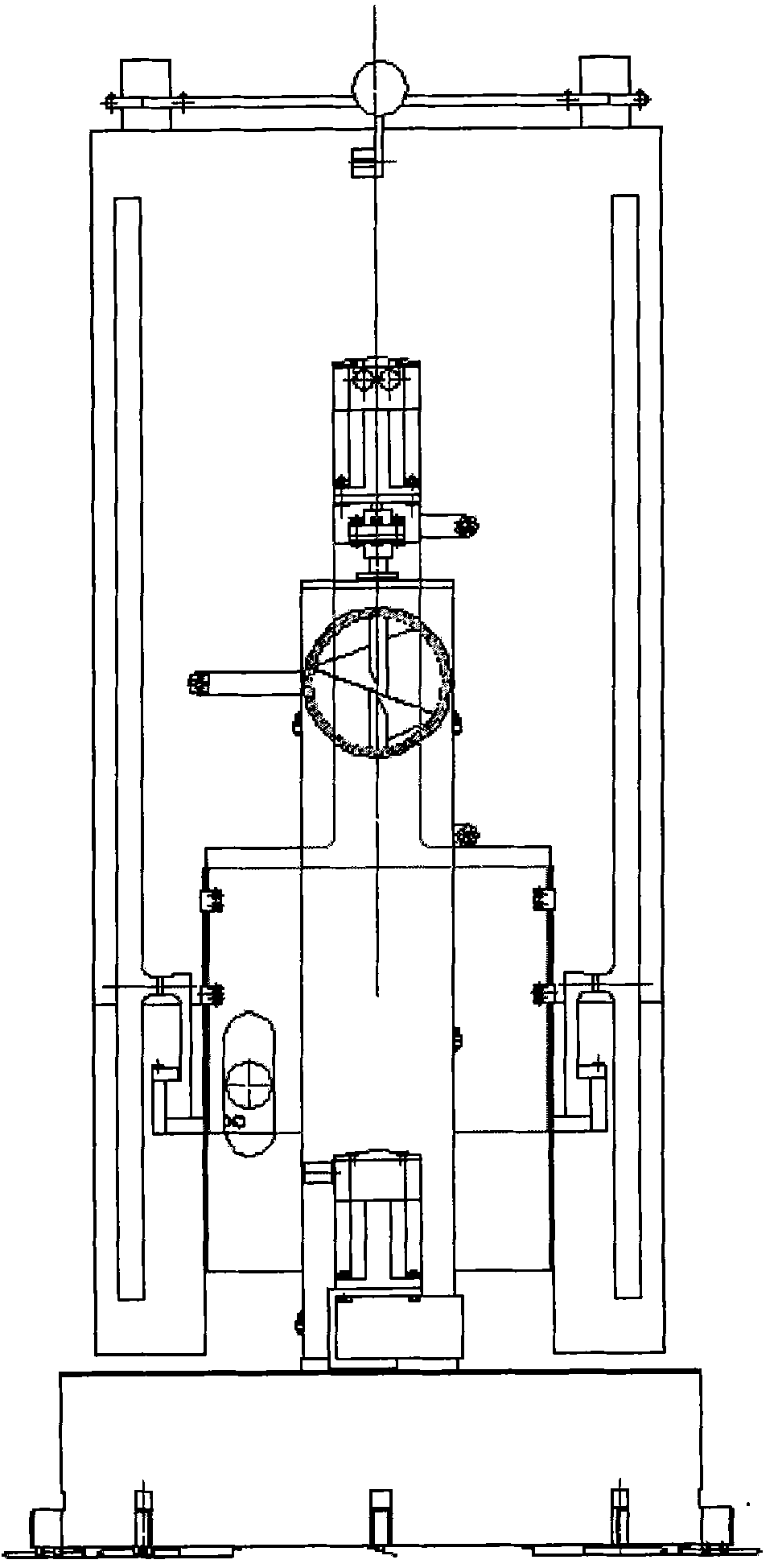
[0022] The present invention is a differential plastering device, which includes a mortar conveying mechanism, a differential plastering mechanism, a swing guide rail mechanism, a dust thickness control device and a universal support trolley; The front end of the sleeve of the screw conveyor 1 is fixed in the axial direction, and is installed on the support frame plate 3 of the swing guide rail mechanism together with the mortar conveying mechanism through the supporting slide plate 2, and together constitutes the core component of the differential plastering device. The core component is hoisted between the two guide rails of the swing guide rail mechanism through the steel wire rope 42 of the hoisting mechanism 29 fixed on the universal support trolley, passing through the fixed pulley 43 instal...


PUM


Abstract

The invention belongs to the technical field of building machinery, and relates to a differential type plastering device. The device comprises a mortar conveying mechanism, a differential plastering mechanism, an oscillation guide rail mechanism, a mortar thickness control device and a universal support cart, wherein the differential plastering mechanism is sleeved at the front end of a sleeve of a helical conveyor of the mortar conveying mechanism, is fixed along the axial direction, and is arranged on a support frame plate of the oscillation guide rail mechanism together with the mortar conveying mechanism through a support sliding plate, thus forming the core component of the differential type plastering device which is formed by variation of a differential wheel system structure; and the spiral conveyer of the mortar conveying mechanism conveys mortar to a centrifugal dash impeller on the end face of a small hollow central gear at the front end of the sleeve, so that the mortar is dashed to the wall surface. The differential type plastering device has a reasonable structure and excellent performance, can well simulate manual plastering, and can realize mechanical plastering for building walls.

Description

technical field [0001] The invention belongs to the technical field of construction machinery, and in particular relates to a differential plastering device for construction. Background technique [0002] Wall plastering is one of the most labor-intensive tasks in building construction. At present, the manual plastering work mode is still widely used at home and abroad. The quality and efficiency of manual plastering depend to a large extent on the worker's operation technology and quality. According to supervision requirements, people have been working on the mechanization of wall plastering for a long time to shorten the construction period and reduce labor costs. So far, more than 200 patents have appeared, but these patents are not actually implemented. According to some of the patents The trial-manufactured plastering equipment generally employs a large number of people, loses a lot of ash, and is cumbersome to operate. The thickness of the mortar on the wall is uneven...

Claims


Application Information

Patent Timeline
IPC IPC(8): E04F21/08
Inventor 范春起刘跃辉
Owner HEBEI UNIVERSITY OF SCIENCE AND TECHNOLOGY
Learn More