

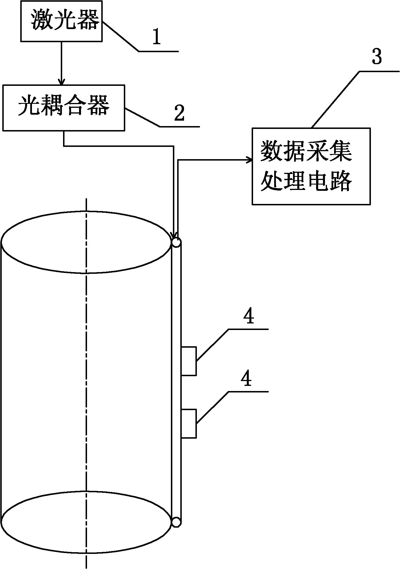
Corrugated diaphragm type pipe external pressure sensor, oil-water well casing external pressure monitoring device and method
The technology of corrugated diaphragm and monitoring device is applied in the direction of fluid pressure measurement of elastic deformation gauge and fluid pressure measurement of optical method, which can solve the problems of real-time online monitoring, etc., and achieves simple structure, high sensitivity coefficient, and easy The effect of manufacture
- Summary
- Abstract
- Description
- Claims
- Application Information
AI Technical Summary
Problems solved by technology
Method used
Image

Examples
specific Embodiment approach 1
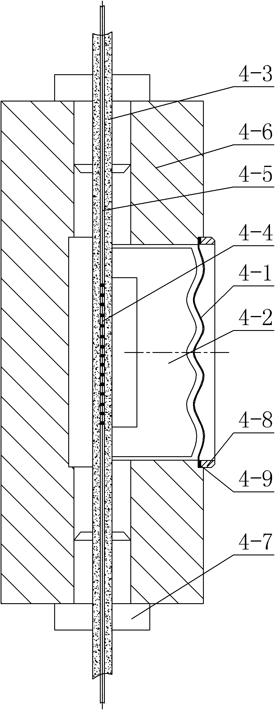
[0019] Specific implementation mode one: the following combination figure 2 Describe this embodiment, the corrugated diaphragm type external pipe pressure sensor described in this embodiment is characterized in that: the corrugated diaphragm type external pipe pressure sensor 4 includes a corrugated diaphragm 4-1, a pressure contact 4-2 , FRP smart rib 4-3, fiber Bragg grating 4-4, optical fiber 4-5, base 4-6 and expansion bolt 4-7,
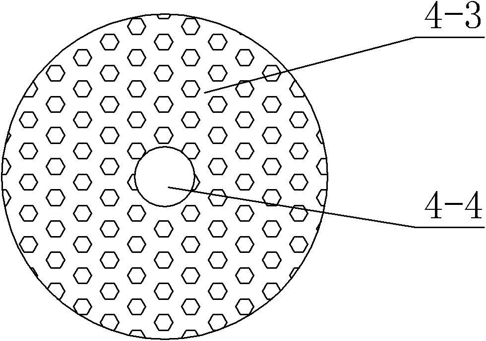
[0020] An optical fiber 4-5 and a fiber Bragg grating 4-4 are arranged in the central cavity of the base 4-6, the fiber Bragg grating 4-4 is located at the center of the central cavity, and the two ends of the fiber Bragg grating 4-4 are respectively arranged The optical fiber 4-5, the outer circular surface of the optical fiber 4-5 and the fiber Bragg grating 4-4 are encapsulated with FRP smart rib 4-3, and the FRP smart rib 4-3 is fixed at both ends of the base 4-6, and the base The two ends of 4-6 clamp the smart tendons 4-3 through ...
specific Embodiment approach 2
[0024] Specific implementation mode two: the following combination figure 2 Describe this embodiment. The difference between this embodiment and Embodiment 1 is that the corrugated diaphragm type external pipe pressure sensor 4 also includes a fastening nut 4-8 and a rubber gasket 4-9. The corrugated diaphragm 4-1 is fixed at the port of the contact hole through a fastening nut 4-8, and a rubber gasket 4-9 is arranged between the corrugated diaphragm 4-1 and the fastening nut 4-8. Other components and connections are the same as those in Embodiment 1.
[0025] The rubber gaskets 4-9 described in this embodiment are standard parts.
[0026] The corrugated diaphragm 4-1 is fixed by the fastening nut 4-8 and the rubber gasket 4-9, which has two functions: one is that it can seal the corrugated diaphragm 4-1, and it is used in the downhole environment When the downhole oil is isolated from the corrugated diaphragm type external pressure sensor 4, a pressure difference is genera...
specific Embodiment approach 3
[0027] Specific implementation mode three: the following combination figure 2 Describe this embodiment, this embodiment is a further description of Embodiment 1 or 2, a groove is provided in the central cavity of the base 4-6, the groove is opposite to the contact hole, and the The axial length of the groove along the optical fiber 4-5 is greater than the axial length of the contact hole along the optical fiber 4-5. Other compositions and connections are the same as those in the first or second embodiment.
[0028] The structural features described in this embodiment make the base 4-6 have strong durability, good reliability and stable performance, which can ensure the detection accuracy.
PUM
| Property | Measurement | Unit |
|---|---|---|
| Linear expansion coefficient | aaaaa | aaaaa |
Abstract
Description
Claims
Application Information