Dynamic loading comprehensive experimental table for gas bearing-rotor system

A technology of gas bearing and system dynamics, which is applied in the direction of mechanical bearing testing, etc., can solve problems such as difficulty in achieving coaxiality, error of gas bearing stiffness measurement results, and inability to guarantee the eccentricity of gas bearing, so as to ensure repeatability and repeatability Strong and easy to disassemble

Inactive Publication Date: 2012-05-16
DALIAN UNIV OF TECH
View PDF2 Cites 4 Cited by
  • Summary
  • Abstract
  • Description
  • Claims
  • Application Information

AI Technical Summary

Problems solved by technology

[0013] (2) Two symmetrically arranged loading bearings (number 9 in the original text) and a test bearing (number 2 in the original text) of the test bench are respectively located on three different bearing seats (supporting devices for bearings), and the loading bearing and test bearing structure are not the same, which makes it difficult for the axes of the three bearings to ensure the required coaxiality, that is, it is difficult to achieve the required coaxiality during processing and installation.
The air film gap of the gas bearing, that is, the eccentricity, is generally between 20-50um. Therefore, the eccentricity of the three gas bearings on the test bench cannot be guaranteed to be within the required accuracy range, and the eccentricity of the gas bearing directly affects the stiffness of the gas bearing. There is a large error...

Method used


Image

  • Dynamic loading comprehensive experimental table for gas bearing-rotor system
  • Dynamic loading comprehensive experimental table for gas bearing-rotor system
  • Dynamic loading comprehensive experimental table for gas bearing-rotor system

Examples


Embodiment Construction

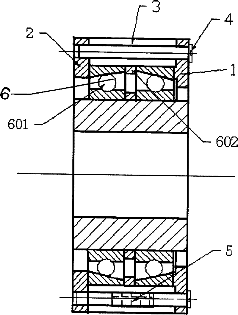
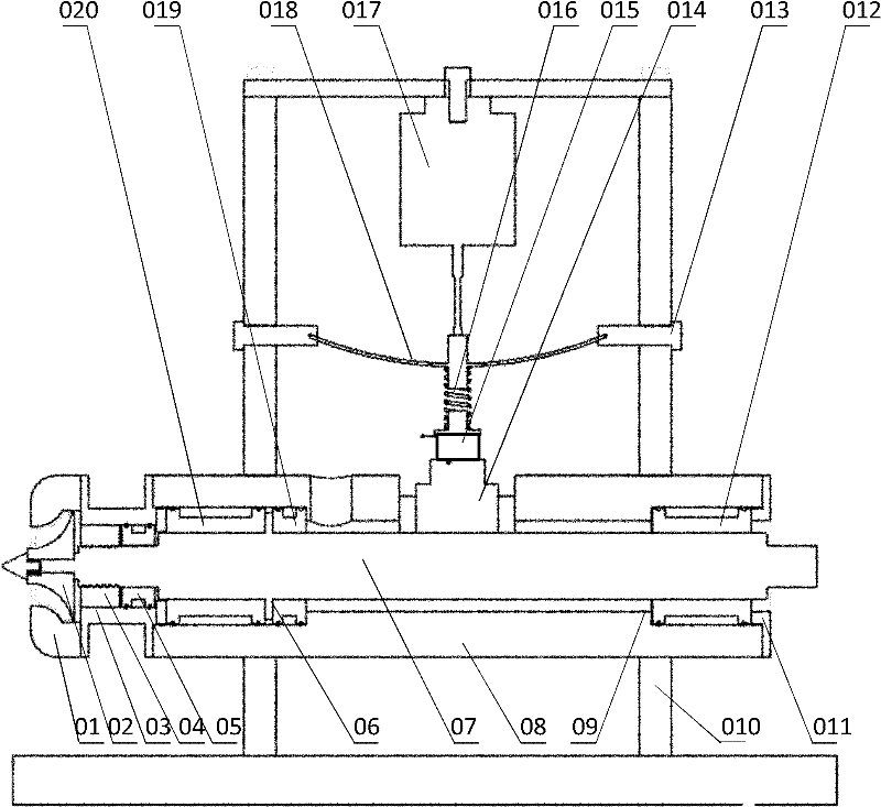
[0049] image 3 It is a schematic structural diagram of the gas bearing-rotor system dynamic loading integrated test bench of the present invention; Figure 4 is a schematic diagram of the tilting pad loading bearing structure; Figure 5 It is a schematic diagram of the bearing disassembly tooling structure. As shown in the figure, the gas bearing-rotor system dynamic loading integrated test bench of the present invention consists of a volute 01, a driving turbine 02, a sealing bracket 03, a labyrinth sealing ring 04, a gas film sealing ring 05, a thrust plate 06, and a rotating shaft 07 , integrated casing 08, boss 09, main support frame 010, cover plate 011, radial gas bearing 012, Charpy beam loading adjustment bolt 013, tilting pad loading bearing 014, force-frequency sensor 015, loading spring 016 , exciter 017, adjustable simply supported beam 018, thrust gas bearing 019, radial-thrust combined gas bearing 020, bearing disassembly tooling 021, etc.; among them, the til...


PUM


Abstract

The invention discloses a dynamic loading integrated experimental table for gas bearing-rotor system and relates to an ultrahigh-speed rotating machine loading technology which is mainly based on the key technologies of an ultrahigh-speed gas bearing supporting module, an integrated foundation supporting structure, a labyrinth-gas film joint sealing structure, static and dynamic loading mechanisms, a rotor system and the like. The experimental table comprises a radial gas bearing, a thrust gas bearing, a radial-thrust joint gas bearing, a bearing disassembling tool, an integrated case, a boss, a cover plate, a sealing bracket, a labyrinth sealing ring, a gas film sealing ring, a main support frame, a vibration exciter, an adjustable simple support beam, a discontinuous variable-cross-section simple support beam, a simple support beam loading adjusting bolt, a loading spring, a force-frequency sensor, a tilting pad loading bearing, a volute, a driving turbine, a thrust disc, a rotatingshaft and the like. The experimental table has the advantages of simple structure, high reliability and strong comprehensiveness, is convenient to assemble and disassemble, and can ensure the gas bearings of the experimental table to be in a fully centered state; and in addition, the static loading force is stable and reliable, and the dynamic loading force and frequency are controllable.

Description

technical field [0001] The invention relates to an ultra-high-speed rotating machine loading technology, and is an experimental platform for studying the static and dynamic characteristics of various ultra-high-speed rotating machine support bearings. Background technique [0002] Rotating machinery has important applications in various fields of the national economy, and the core component of rotating machinery support is the bearing. Currently commonly used bearing types are oil-lubricated sliding bearings, rolling bearings, ceramic bearings, electromagnetic bearings, gas bearings, etc. Gas bearing is a high-tech product developed rapidly in the middle of the 20th century. Compared with traditional rolling bearings or oily sliding bearings, it has high speed, high precision, low power consumption, no pollution, long life and strong environmental adaptability. Etc. Therefore, it is widely used in national defense, energy, machine tools and medical industries, especially i...

Claims


Application Information

Patent Timeline
IPC IPC(8): G01M13/04
Inventor 刘艳赵广王巍刘健陈锋于贺春马文琦
Owner DALIAN UNIV OF TECH
Why Eureka
Try Eureka