Storage battery with simultaneously rechargeable unit cells and multipath parallel-connected charger

A charging circuit and battery technology, applied in battery circuit devices, secondary battery charging/discharging, circuits, etc., can solve problems such as heat loss, large interaction of battery cells, inconsistent internal resistance, etc., to speed up charging , fast charging without damage, not easy to dehydration vulcanization effect

Inactive Publication Date: 2011-07-13
罗征南
View PDF3 Cites 7 Cited by
  • Summary
  • Abstract
  • Description
  • Claims
  • Application Information

AI Technical Summary

Problems solved by technology

[0004] First, it is doomed that the cells of the battery will have a great influence on each other during charging. Due to the high manufacturing requirements of the battery and the complicated process, it is difficult to ensure that the capacity and internal resistance of each cell of the battery are exactly the same, that is, The balance between the cells, in the charging process of the battery, will produce the capacity of one or several cells, the internal resistance is inconsistent, the voltage is high or low, resulting in overcharging or undercharging, so that the defective cells Overcharging or undercharging will accelerate dehydration or vulcanization, and the capacity will decrease. After a period of use, it will soon affect the adjacent

Method used


Image

  • Storage battery with simultaneously rechargeable unit cells and multipath parallel-connected charger
  • Storage battery with simultaneously rechargeable unit cells and multipath parallel-connected charger
  • Storage battery with simultaneously rechargeable unit cells and multipath parallel-connected charger

Examples


Embodiment Construction

[0027] The combined invention will be described in further detail below in conjunction with the accompanying drawings and specific embodiments:

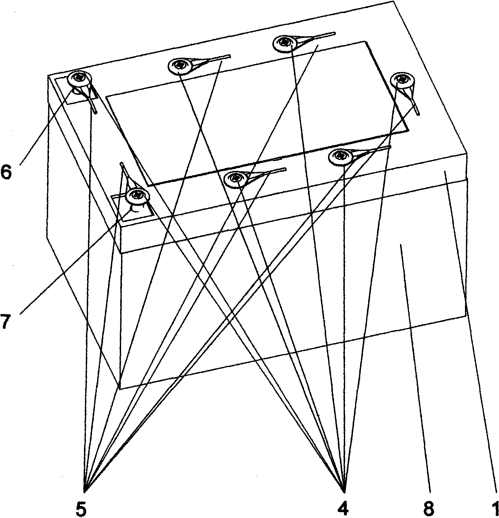
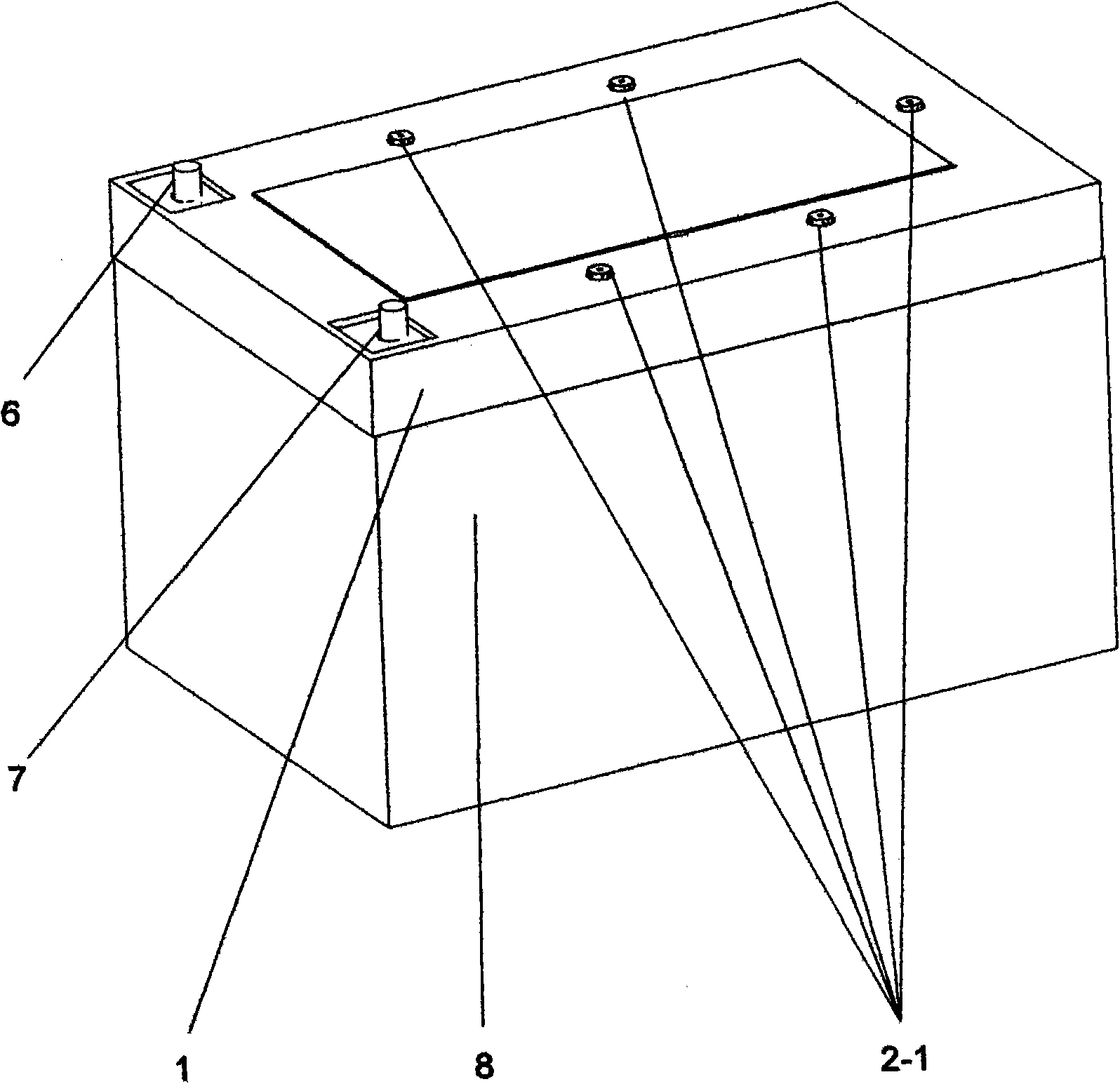
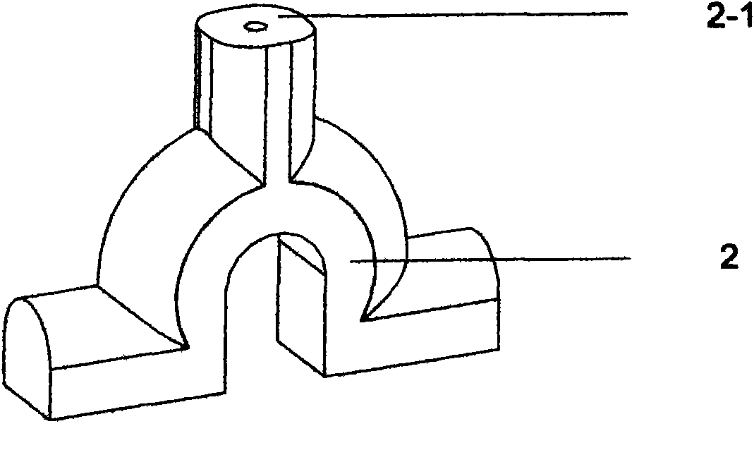
[0028] A storage battery that can be directly and simultaneously charged in a single cell, including a casing, positive and negative plates, separators, positive and negative bus bars, bridges, tabs, upper cover, electrolyte, etc. Taking the 12v electric vehicle battery as an example, refer to figure 1 , figure 2 , image 3 , Figure 4 , Figure 5 In the 5 bridges of the 6 cells of the storage battery, a rechargeable bridge 2 similar to the shape of a "herringbone" is used to replace the bridge 3 between each cell in the original battery structure, and the "herringbone" shape is added. The pole 2-1 at the upper end of the bridge has the function of connecting the charging wire 5, and the two lower ends have the same function as the original bridge and are still respectively connected to the negative pole and the positive pole of...


PUM


Abstract

The composite invention discloses a storage battery with simultaneously rechargeable unit cells and a multipath parallel-connected charger, and aims to provide a more ideal storage battery and a corresponding charging method for electric automobiles. The storage battery with simultaneously rechargeable unit cells comprises a storage battery shell, a positive plate, a negative plate, a separation plate, a positive bus bar, a negative bus bar, a gap bridge, a tab, an upper cover, electrolyte, a power circuit, a positive and negative pulse charging circuit, a unit cell detection circuit, a central processing unit (CPU) main control circuit and a power control circuit; a pole at the upper end of the rechargeable gap bridge of the storage battery passes through a connecting hole on the upper cover of the storage battery and then is connected with a charging lead wire by a screw, so the unit cells of the storage battery can be charged; and the same number of relatively independent charging power supplies are made for the charger according to the number of the unit cells of the storage battery. By the storage battery with the simultaneously rechargeable unit cells, the charging speed is increased, and the charging time is shortened, so the voltage of the storage battery or the storage battery group is more balanced or more sufficient; and adverse influences that some unit cells are overcharged and heated and some unit cells are charged insufficiently when the unit cells of the storage battery are charged in the conventional serial charging mode are eliminated.

Description

technical field [0001] The combined invention relates to the manufacturing process of accumulators and related multi-channel parallel chargers, in particular to the charging method of various accumulators used as power type and traction type represented by electric vehicles and related parallel chargers. Background technique [0002] At present, all kinds of storage batteries commonly used at home and abroad have defects such as easy loss of water, easy vulcanization, easy overcharging, and undercharging to varying degrees, so that the life of the battery generally does not meet the design requirements. At the same time, it generally takes a long time to charge, and it is impossible to charge quickly without damage in a short time. The reason: people's concept of battery design, manufacture and related charging methods is still stuck in the traditional thinking, and the traditional old way of more than 100 years is still used, that is, the link between cells inside the batte...

Claims


Application Information

Patent Timeline
IPC IPC(8): H01M10/46H01M10/44H02J7/00
CPCY02E60/12Y02E60/10
Inventor 罗征南
Owner 罗征南
Why Eureka
Try Eureka