Depth projector system with integrated vcsel array

A technology of projectors and arrays, applied in the field of depth projector systems with integrated VCSEL arrays, which can solve the problems of high cost, damage and failure of projectors, and time-consuming problems

Active Publication Date: 2011-07-20
MICROSOFT TECH LICENSING LLC
View PDF4 Cites 55 Cited by
  • Summary
  • Abstract
  • Description
  • Claims
  • Application Information

AI Technical Summary

Problems solved by technology

Assembling these components together is time consuming and costly...

Method used


Image

  • Depth projector system with integrated vcsel array
  • Depth projector system with integrated vcsel array
  • Depth projector system with integrated vcsel array

Examples


Embodiment Construction

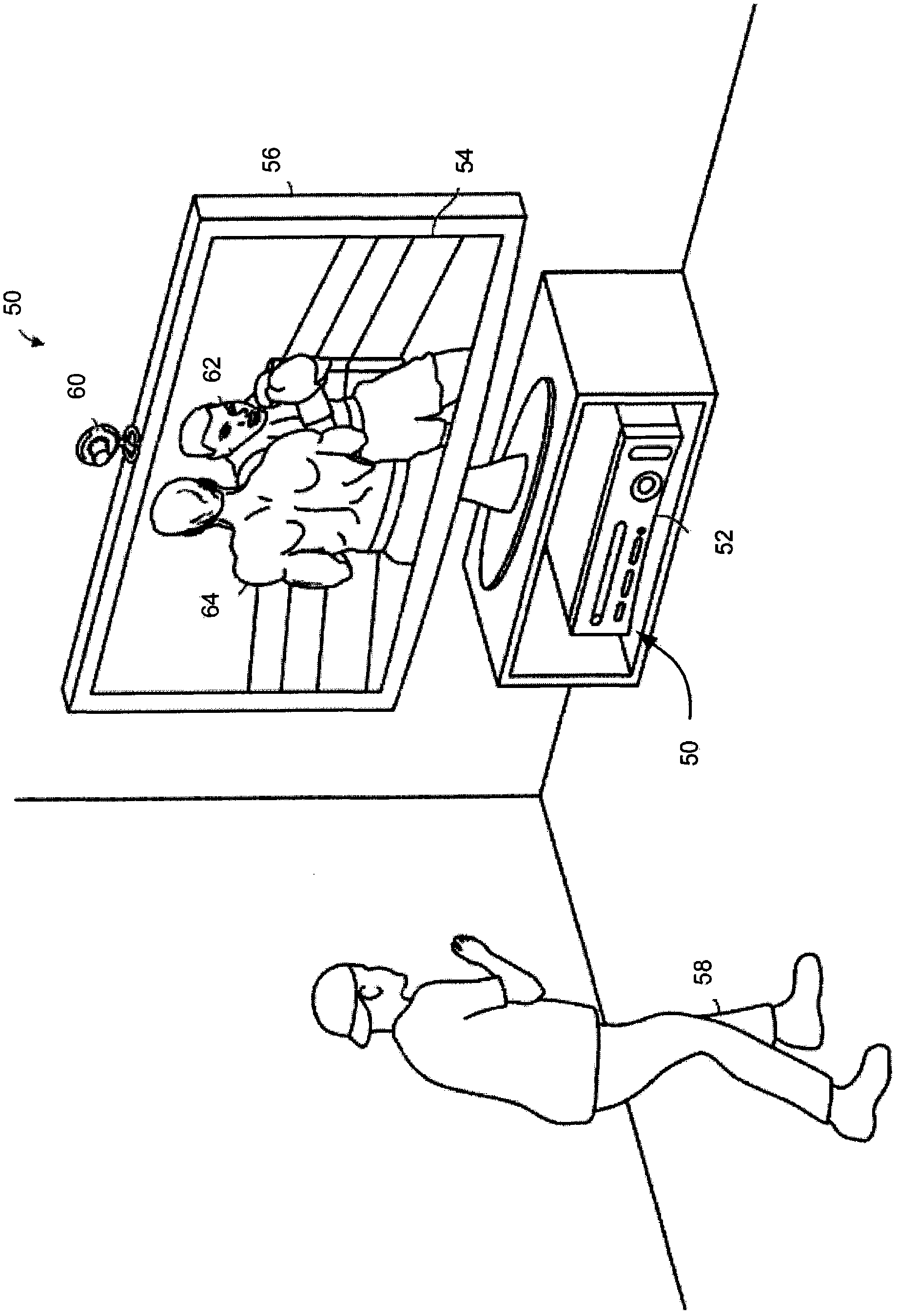
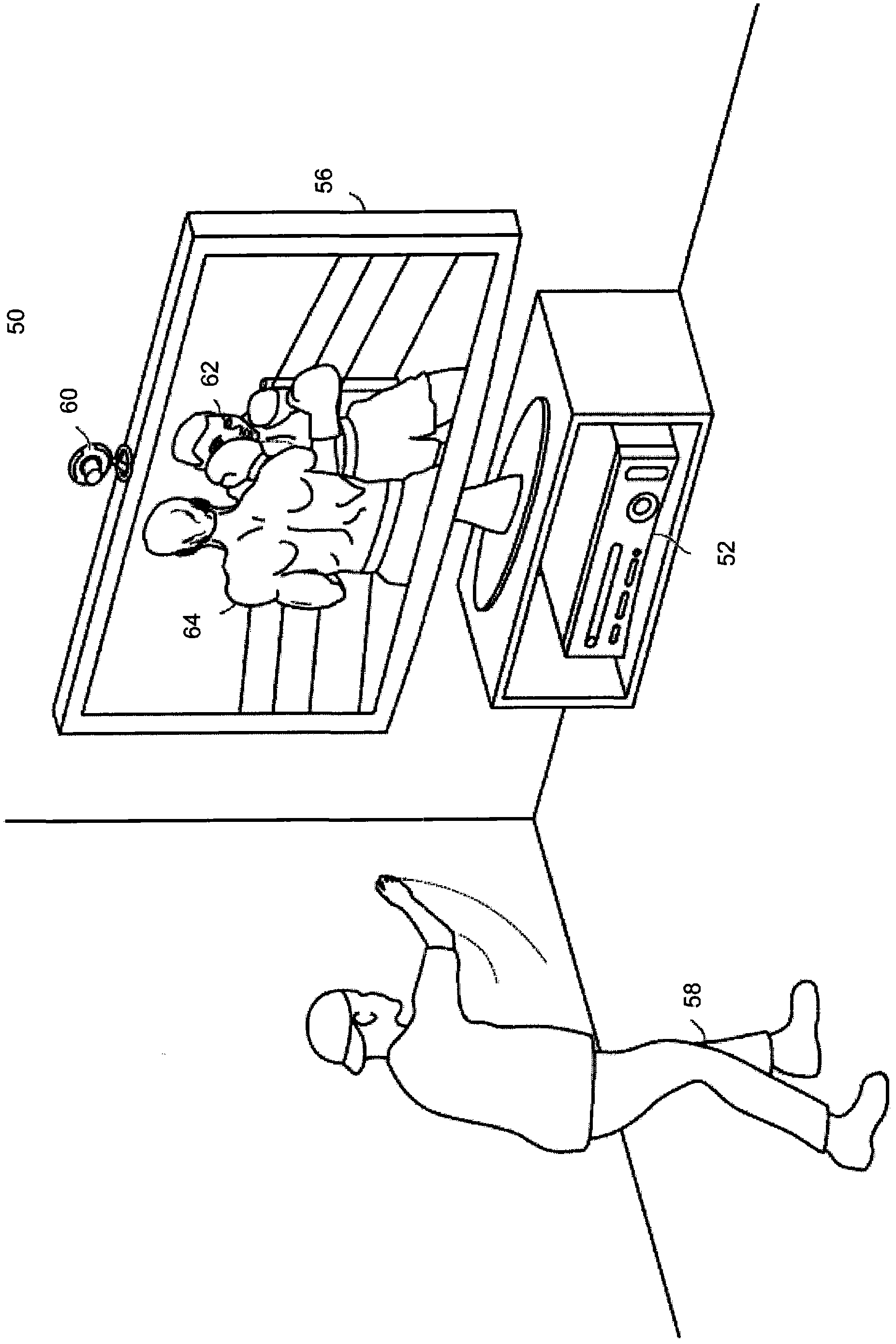
[0045] will now refer to Figures 1A to 39 Various embodiments of the inventive technique are described, which generally relate to a 3-D capture device including a projection system utilizing a VCSEL array. Figure 1A and 1B One example of system 50 is shown in which a 3-D capture device 60 according to the techniques of the present invention can be used to identify, analyze and / or track objects such as human targets, such as user 58 . Embodiments of system 50 also include a computing environment 52 for executing games or other applications, and audio-visual devices 56 for providing audio and visual representations from games or other applications. The computing environment receives feedback from capture device 60 and uses the feedback to control a game or other application. As explained below, capture device 60 includes a projector using a VCSEL array in accordance with the techniques of the present invention.

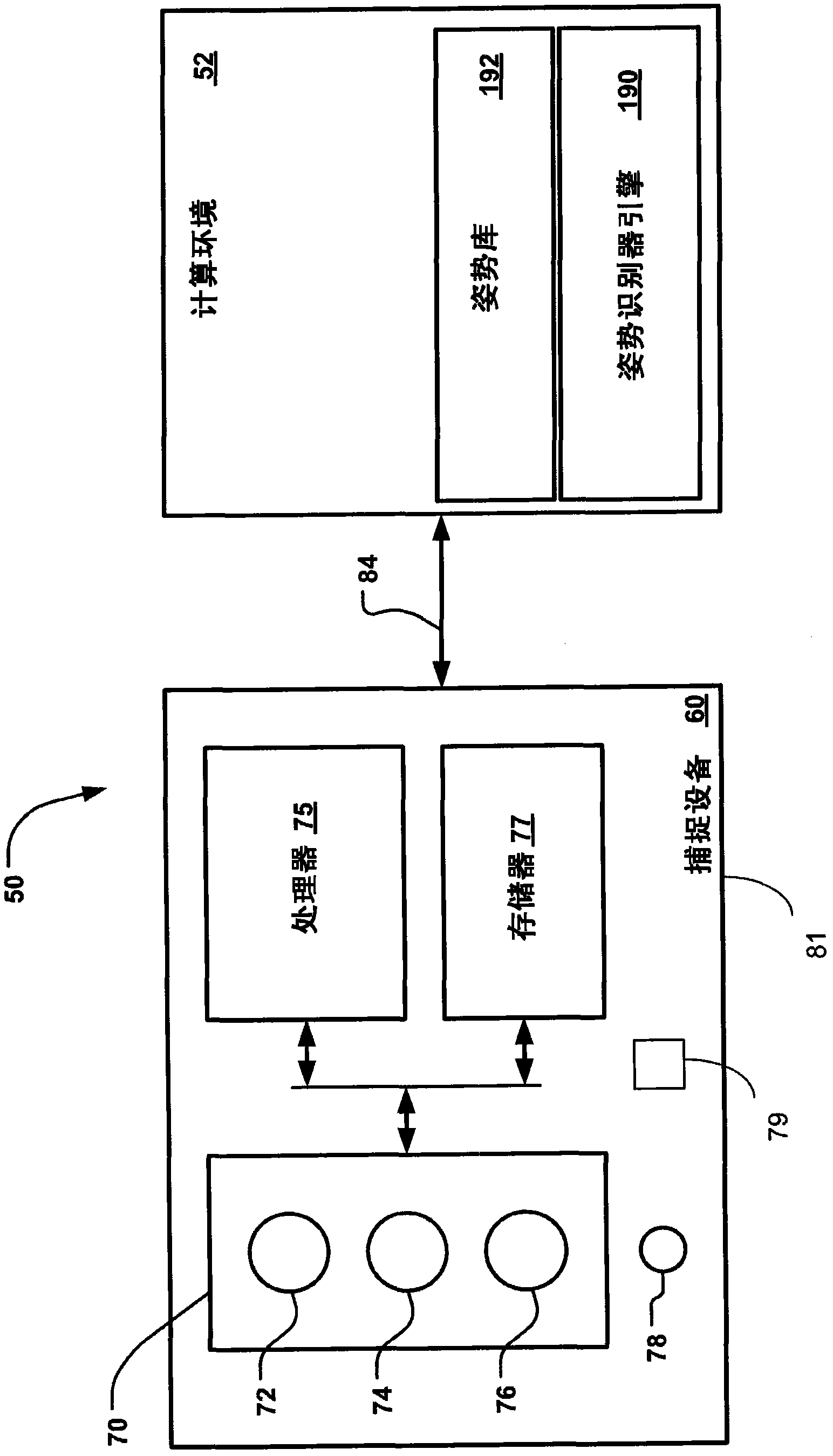
[0046] Various embodiments of the computing environment 52 ar...


PUM


Abstract

The present invention discloses a projector used in 3-D imaging equipment. The projector comprises a light source which is formed by a transmission laser on a surface of a vertical chamber, namely a VCSEL array. The VCSEL array comprises a light source which is used for illuminating a capturing area. The light from the VCSEL array is reflected on an object on the capturing area, and is received in sensing equipment such as a 3-D camera, etc. The projector furthermore can comprise a collimating lens array which is used for focusing the light that is transmitted from each VCSEL, and a DOE which is used for patterning the light from the collimating lens so the sensing equipment can generate the object in the capturing area.

Description

Background technique [0001] Three-dimensional optical imaging systems are capable of providing distance measurements and depth images of objects within the capture area. Such systems are currently used, for example, in gaming and multimedia applications to provide human identification and gesture recognition, and in a variety of other applications such as inspection of semiconductors and other commodities, CAD verification, robotic vision, and geographic surveying . Generally, three-dimensional (3-D) imaging systems include a projector with a light source for illuminating a scene (object). The 3-D imaging system also includes a receiver, such as a 3-D camera, for receiving light reflected from the object and for forming a 3-D image of the object from the reflected light. [0002] Existing approaches to implementing depth projectors utilize laser diodes assembled as Transistor Outline Packages (TO-Cans) with collimating optics and diffractive optical elements (DOEs) to encode...

Claims


Application Information

Patent Timeline
IPC IPC(8): G03B17/54G03B35/00G06F3/01
CPCG06F3/017G03B35/00G03B17/54G06F3/005G03B21/14G06F3/011G03B35/08G03B21/2033
Inventor S·麦克尔道尼
Owner MICROSOFT TECH LICENSING LLC
Why Eureka
Try Eureka