Image surface driving point-based imaging method of optical remote sensor

An optical remote sensor and imaging method technology, applied in the field of optical remote sensing, can solve problems such as large amount of calculation

Active Publication Date: 2012-11-14
北京航天创智科技有限公司
View PDF0 Cites 0 Cited by
  • Summary
  • Abstract
  • Description
  • Claims
  • Application Information

AI Technical Summary

Problems solved by technology

This model physics requires considerable computational

Method used


Image

  • Image surface driving point-based imaging method of optical remote sensor
  • Image surface driving point-based imaging method of optical remote sensor
  • Image surface driving point-based imaging method of optical remote sensor

Examples


Embodiment Construction

[0032] Below in conjunction with accompanying drawing and specific embodiment, the present invention is described in further detail:

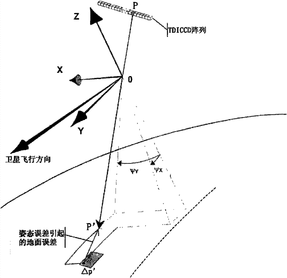
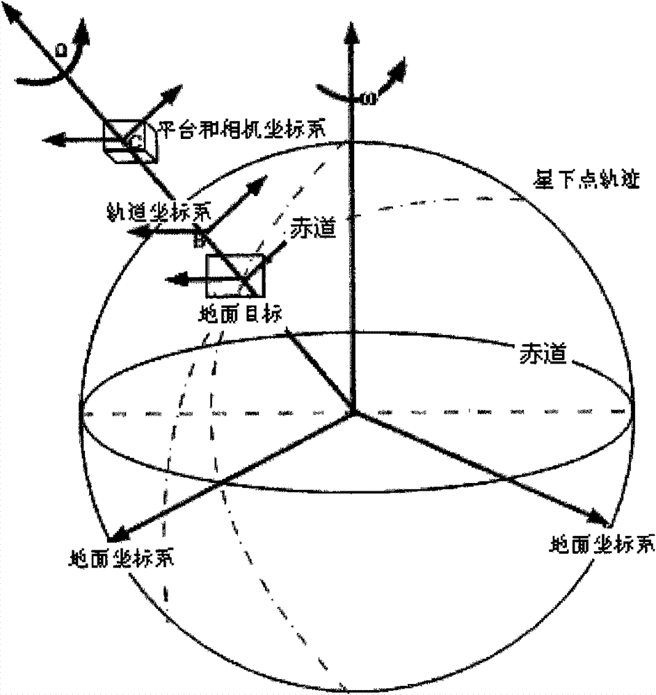
[0033] like figure 1 Shown is the optical remote sensor imaging geometric topology relationship diagram. The theoretical basis of the linear optical remote sensor model is as follows: The imaging position of any point P on the image plane in space can be approximated by the pinhole model, that is, the The projection position of point p' on the image plane is p, and p is the intersection point of the line OP connecting the optical centers O and P of the camera with the image plane.

[0034] figure 1 , (x, y, z) are the coordinates of the TDICCD optical remote sensor, O is the origin of the optical remote sensor coordinate system, the blue arrow is the flight direction of the satellite, Ψ y is the yaw angle, Ψ x is the pitch angle. where Δp' is the ground error offset distance due to attitude error.

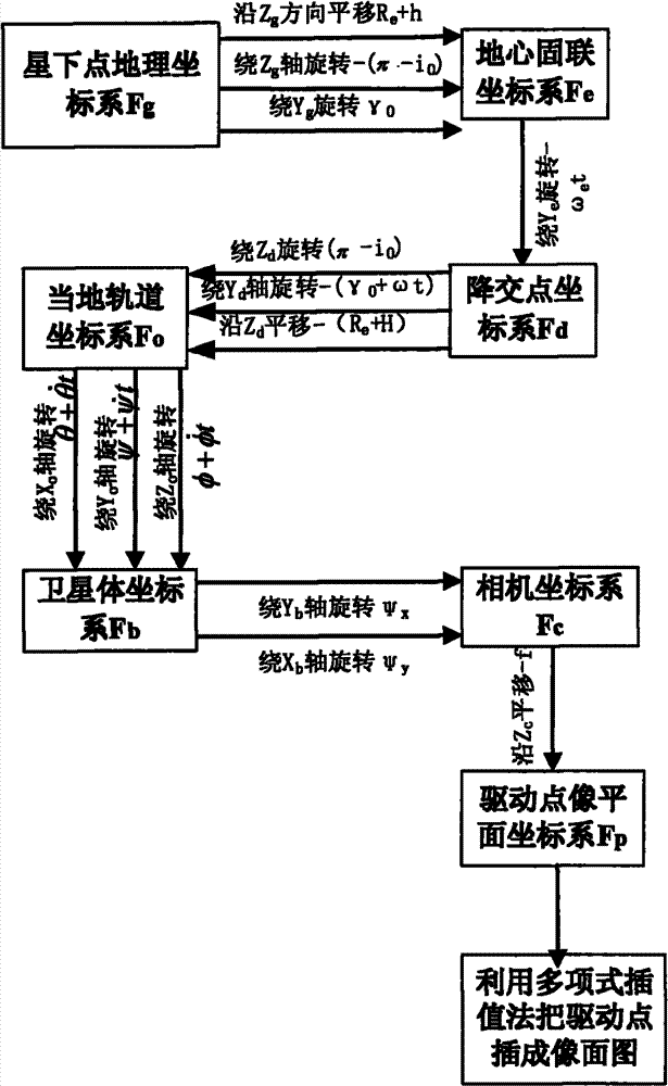
[0035] The imaging model of the linear o...


PUM


Abstract

The invention relates to an image surface driving point-based imaging method of an optical remote sensor. The method comprises the steps of: establishing a platform optics payload geometric distortion model by utilizing a method of coordinate transformation according to a physical model transformed from a ground coordinate system to an image surface coordinate system; , fitting a small quantity of image surface driving points into an image by utilizing polynomial interpolation; and by utilizing the model, completing the imaging of the model in different postures and analyzing the image geometric distortion caused by the postures. Therefore, the effect transformation between an object surface and an image surface is realized; the calculation amount is reduced and a higher precision is maintained; meanwhile, the problem of overlarge calculation complexity in a traditional precise geometrical model is solved and the shortcoming of lacking physical meaning in a rational function model is made up.

Description

Technical field: [0001] The invention belongs to the technical field of optical remote sensing, and particularly relates to an imaging method of an optical remote sensor based on an image plane driving point. Background technique [0002] High-resolution optical remote sensors have very demanding platform requirements. Existing transmission-type space remote sensors usually use linear CCD push-broom imaging. The push-broom imaging is very sensitive to the geometric distortion of the image caused by the unstable attitude. The image distortion caused by the attitude change is divided into three directions: roll, pitch and yaw. The attitude changes cause the projection of the linear array CCD on the ground to be distorted. In particular, it is more sensitive to the influence of high-resolution optical remote sensors. To analyze the relationship between the motion error of the satellite platform and the imaging mapping, it is necessary to establish a geometric model between th...

Claims


Application Information

Patent Timeline
Patent Type & Authority Patents(China)
IPC IPC(8): G06T3/00G01S7/48
Inventor 张智刘兆军周峰
Owner 北京航天创智科技有限公司
Why Eureka
Try Eureka